658
Chapter 32 USART (LIN / FIFO)
7.USART Operation
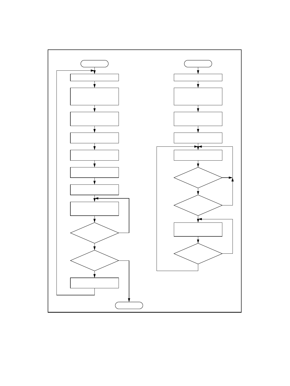
Figure 7-12 Master-slave communication flowchart
Start
Set operation mode 1
Set SIN pin as the
serial data input pin.
Set SOT pin as the
serial data output pin.
Set 7 or 8 data bits.
Set 1 or 2 stop bits.
Set “1” in AD bit
Set TXE = RXE = 1.
Send Slave Address
Set “0” in AD bit.
Communicate with
slave CPU
Is
communication
complete?
Communicate
with another
slave CPU?
Set TXE = RXE = 0.
End
NO
YES
NO
YES
(Master CPU)
Start
Set operation mode 1
Set SIN pin as the
serial data input pin.
Set SOT pin as the
serial data output pin.
Set 7 or 8 data bits.
Set 1 or 2 stop bits.
(Slave CPU)
Set TXE = RXE = 1.
Receive Byte
Is
AD bit = 1 ?
Does
Slave Address
match?
Communicate with
master CPU
Is
communication
complete?
NO
NO
NO
YES
YES
YES


