375
Chapter 26 DMA Controller
4.Operation Flowcharts
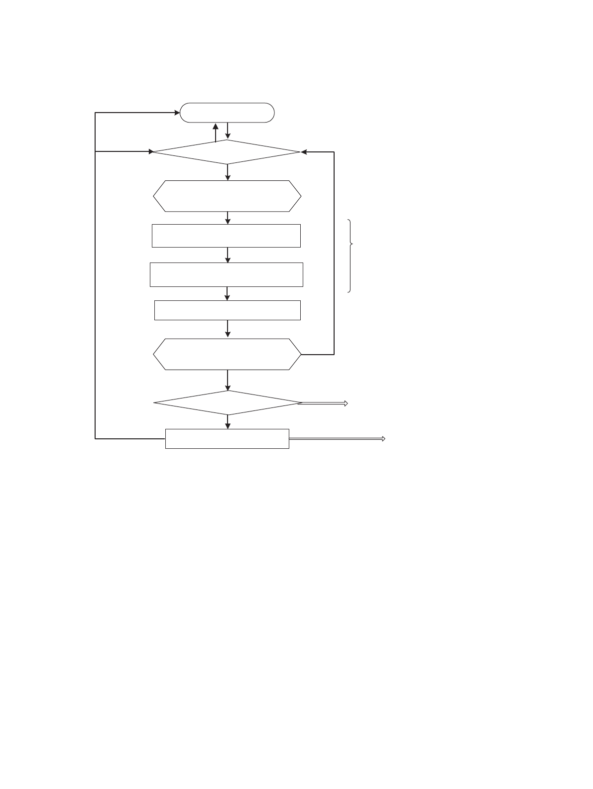
Figure 4-3 Operation Flowchart for Demand Transfer
Load the initial address,
transfer count, and
number of blocks
Activation request
wait
DMA transfer end
DMA interrupted
DTC=0
DMA stop
DENB=1
DENB=>0
Write back the address,
transfer count, and number
of blocks
Interrupt clear
Activation request
One-time access for fly-by
Reload enable
Only when the peripheral interrupt
activation source is selected
Calculate the address for
transfer source address access
Calculate the address for transfer
destination address access
Number of transfer - 1
Interrupt cleared
None
Demand transfer
- Only requests (level detection) from the external pin (DREQ) are accepted. Activation by
other sources is disabled.
- Access to an external area is required (since access to an external area becomes the
next activation source).
- The number of blocks is always 1, regardless of the settings.
- Interrupt clear and the DMA interrupt are issued when transfer for the number of times
specified is completed.


