


652
Chapter 32 USART (LIN / FIFO)
7.USART Operation
• BDS: "0" for LSB first,
"1" for MSB first
• RIE: "1" if interrupts are used
"0" if not
• TIE: "1" if interrupts are used
"0" if not
• Extended Communication Register (ECCR04):
• SSM: "0" if no start/stop bits are desired (normal)
"1" for adding start/stop bits (special)
• MS: "0" for master mode (USART generates the serial clock);
"1" for slave mode (USART receives serial clock from the master device)
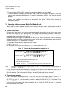
To start the communication, write data into the Transmission Data Register (TDR04).
To receive data, disable the Serial Output Enable (SOE) bit of the SMR04 and write dummy data to TDR04.
(Note) Setting continuous clock and start-/stop-bit mode, duplex transception is possible like in
asynchronous modes.
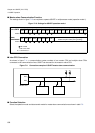
7.3 Operation with LIN Function (Operation Mode 3)
USART can be used either for LIN-Master devices or LIN-Slave devices. For this LIN function a special mode
(3) is provided. Setting the USART to mode 3, configure the data format to
8N1-LSB-first format.
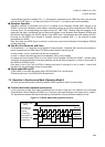
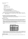
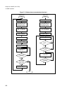
■ USART as LIN master
In LIN master mode, the master determines the baud rate of the whole sub bus. Therefore, slave devices have
to synchronize to the master and the desired baud rate remains fixed in master operation after initialization.
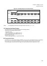
Writing a "1" into the LBR bit of the Extended Status/Communication Register (ECCR04) generates a 13 - 16
bit times low-level on the SOT04 pin, which is the LIN synchronization break and the start of a LIN message.
Thereby the TDRE flag of the Serial Status Register (SSR04) goes "0" and is reset to "1" after the break, and
generates a transmission interrupt for the CPU (if TIE of SSR04 is "1").
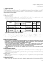
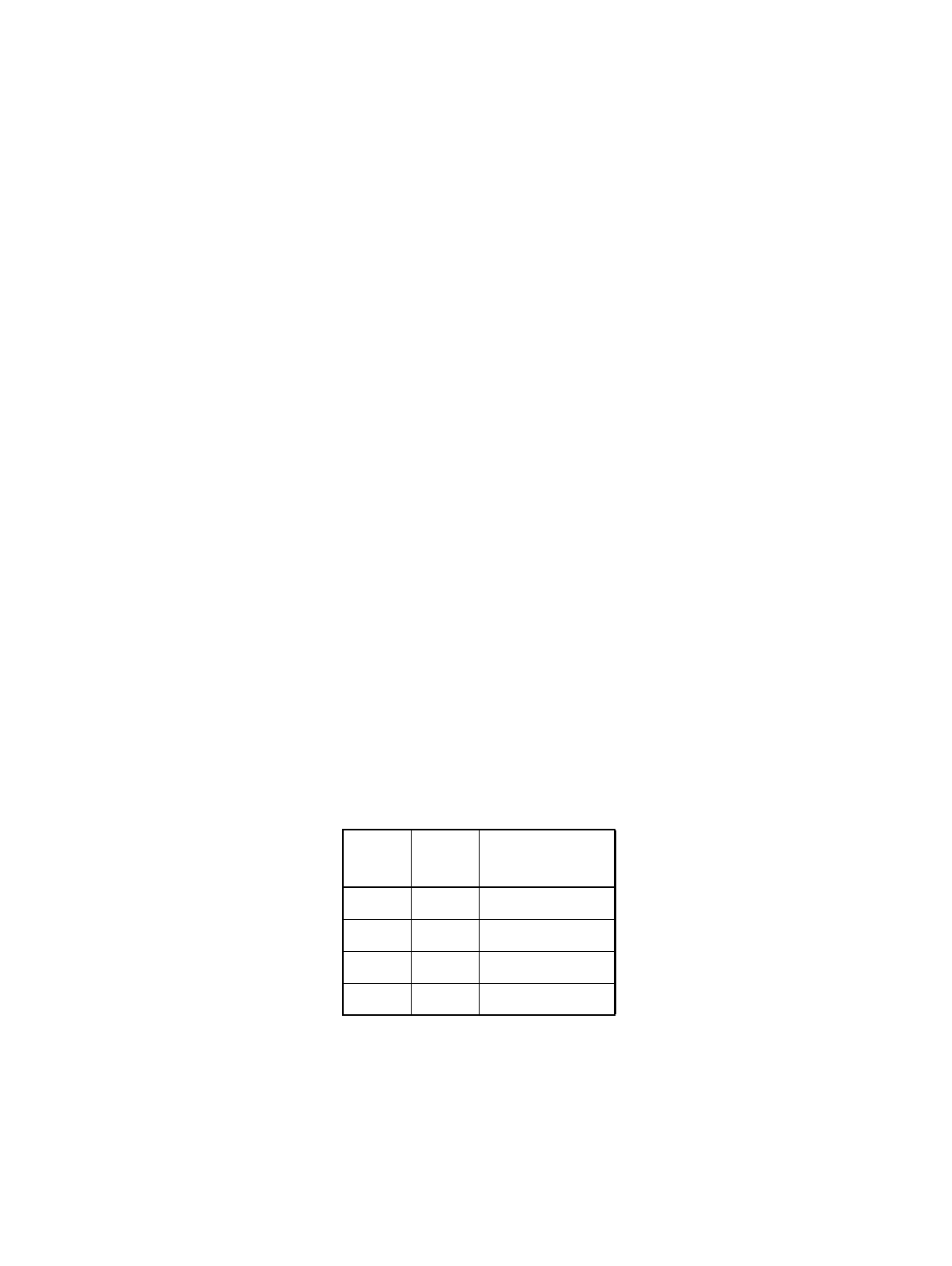
The length of the Synchronization break to be sent can be determined by the LBL1/0 bits of the ESCR04 as
follows:
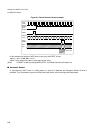
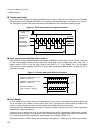
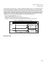
The Synch Field can be sent as a simple 0x55-Byte after the LIN break. To prevent a transmission interrupt,
the 0x55 can be written to the TDR04 just after writing the "1" to the LBR bit, although the TDRE flag is "0".
The internal transmission shifter waits until the LIN break has finished and shifts the TDR04 value out
afterwards. In this case no interrupt is generated after the LIN break and before the start bit.
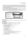
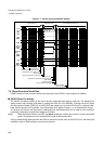
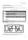
■ USART as LIN slave
In LIN slave mode USART has to synchronize to the master’s baud rate. If Reception is disabled (RXE = 0) but
Table 7-2 LIN break length
LBL1 LBL0
Length of
Break
0 0 13 Bit times
0 1 14 Bit times
1 0 15 Bit times
1 1 16 Bit times