


291
Chapter 22 Main Oscillation Stabilisation Timer
4.Register
4. Register
4.1 OSCRH: Control Register for the Main Clock Oscillation Stability Wait Timer
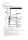
This register is used to select the interval time, clear the timer, control the interrupt, control the timer such as
stop, and confirm the state of the timer.
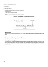
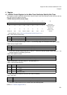
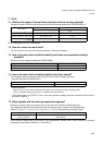
• OSCRH: Address 04C8h (Access: Byte)
(For the attributes, refer to “Meaning of Bit Attribute Symbols (Page No.10)”.)
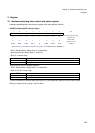
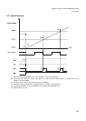
• Bit7: Timer interrupt request flag
• The timer interrupt request flag bit is set to “1” at the falling edge of the selected interval period output.
• Bit6: Interrupt request enable
• If the timer interrupt request flag (WIF) is set to “1” while the interrupt request enable (WIE) is “1” an
interrupt request is immediately generated.
• Bit5: Timer operation enable
• Bit4-3: Reserved bit Be sure to write “0”. The read value is “0”.
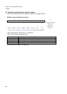
• Bit2-1: Interval period selection
• The reset does not initialize. Be sure to set it after the startup.
• Bit0: Timer clear
• The timer is also cleared by INITX terminal input and watchdog reset.
(Refer to “8. Caution (Page No.297)”.)
7 6543210 bit
WIF WIE WEN – – WS1 WS0 WCL
0 00XX001
Initial value
(INIT terminal input,
watchdog reset)
XXXXXXXX
Initial value
(Software reset)
R(RM1),W R/W R/W RX/W0 RX/W0 R/W R/W R1,W Attribute
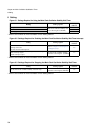
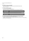
WIF Read Operation Write Operation
0 Without interrupt request Clears interrupt request flags
1 With interrupt request Writing does not affect operation
WIE Operation
0 Interrupt request disable
1 Interrupt request enable
WEN Operation
0 Stops timer operation
1 Enables timer operation
WS1 WS0 Interval period (At 4MHz)
0 0 Setting prohibted
01
2
12
/F
CL-MAIN
(1.0ms)
10
2
17
/F
CL-MAIN
(32.7ms)
11
2
23
/F
CL-MAIN
(2.0s)
WCL Operation
0 Clears the main clock oscillation stability wait timer
1 Writing does not affect operation