


849
Chapter 41 Up/Down Counter
5.Operation
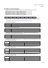
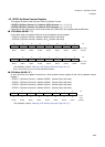
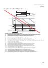
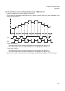
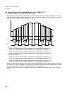
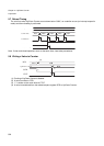
5.2 Up/Down Count Mode CMS[1:0]=“01”
Up/Down Counter clear control using the ZIN pin
(1) Appropriate bits (Counting enable CSTR, Reload enable RLDE, Clear enable UCRE) are set.
(2) When pulse input to the AIN pin is detected, Up/Down Counter counts up.
(3) The count direction change flag is set to “1”.
(4) When an edge is applied to the ZIN pin, Up/Down Counter is cleared.
(5) Continuous pulse input to the AIN pin causes Up/Down Counter to count up.
(6) The Up/Down Counter's count value agrees with the compare value (compare-match) and the
compare-match flag is set to “1”.
(7) Compare-match clears Up/Down Counter.
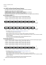
(8) Continuous pulse input to the AIN pin causes Up/Down Counter to count up.
(9) When pulse input to the AIN pin stops, Up/Down Counter stops counting.
(10) When pulse input to the BIN pin is detected, Up/Down Counter counts down.
(11) The count direction change flag is set to “1”.
(12) Continuous pulse input to the BIN pin causes Up/Down Counter to count down.
(13) Up/Down Counter is underflowed and the underflow flag is set to “1”.
(14) The underflow causes the reload value to be reloaded to Up/Down Counter.
(15) Next time when Up/Down Counter counts down, the compare-match flag is set to “1”.
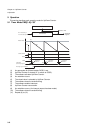
F
CLKP
divided by 2
F
CLKP
divided by 8
Reload value
Countdown
Interrupt
request
enabled
Reload value
Reload value
CLKS, RLDE
CGSC
CSTR
Interrupt request enabled
Underflow
(Interrupt request)
Cleared by
software
Cleared by
software
Cleared by
software
(1)
(2)
(8)
(7)
(6)
(5)
(4)
(3)
(3)
(9)
(9)
(10)