


307
Chapter 23 Sub Oscillation Stabilisation Timer
7.Q & A
7. Q & A
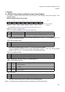
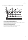
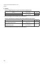
7.1 What are the types of interval time (wait time) and how are they selected?
There are three types of interval time, and they are set with the interval selection bit (WPCRH.WS[1:0]).
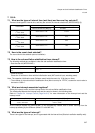
7.2 How is the count clock selected?
The count clock is the subclock (source oscillation).
7.3 How is the sub oscillation stabilisation timer cleared?
The following methods are available to clear the sub oscillation stabilisation timer.
• Sets the clear bit (WPCRH.WCL).
• Performs a reset.
Clears the 15-bit free run timer with the initialization reset (INIT terminal input, watchdog reset).
Note: The operation initialization reset (Software reset) holds the count of a 15-bit free run timer.
• The overflow of the sub oscillation stabilisation timer (Next count-up for “FFFFh”) causes the count value to
be reset to “0000
H
”.
7.4 What are interrupt-associated registers?
Setting the interrupt vector and the interrupt level of the sub oscillation stabilisation timer
The relationship between the interrupt level and the vector is shown in the following table.
Refer to “Chapter 24 Interrupt Control (Page No.311)” for more information on the interrupt level and the
interrupt vector.
As the interrupt request flag (WPCRH.WIF) is not automatically cleared, clear it before returning from the
interrupt processing by the software. (Writes “0” to the WIF bit.)
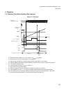
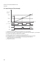
7.5 What are the types of interrupt?
There is one type for the interrupt, and it is generated with the interval time (Subclock oscillation stability wait).
Interval time
Count period Interval (Wait time) Example
Interval selection bit (WS[1:0])
F
CL-SUB
= 32.768kHz
To set the interval time to
2
10
/F
CL-SUB
Set the value to “00”. 31.25ms
To set the interval time to
2
13
/F
CL-SUB
Set the value to “01”. 0.25s
To set the interval time to
2
14
/F
CL-SUB
Set the value to “10”. 0.50s
To set the interval time to
2
15
/F
CL-SUB
Set the value to “11”. 1.00s
Operation Clear bit (WCL)
To clear the sub oscillation stabilisation
timer
Writes “1”
Interrupt vector (Default) Interrupt level setting bit (ICR[4:0])
#143
Address: 0FFDC0h
Interrupt level register (ICR63)
Address: 047Fh