


200
Chapter 13 Clock Control
5.Operation
5.3 Notes
■ Main PLL control
After initialization, the main PLL oscillation is halted. While halted, the output of the main PLL cannot be
selected as the clock source.
After the program starts, first set the multiplier for the main PLL that you want to use as the clock source and
then, after allowing a time for the main PLL to lock, change the clock source. The recommended method for
waiting for the main PLL to lock is to use the timebase timer interrupt.
You cannot halt the main PLL while the output of the main PLL is selected as the clock source.
Writing to the register has no effect. If you wish to stop the main PLL such as when changing to stop mode,
first select the main clock divided by 2 as the clock source and then halt the main PLL.
If the main clock oscillation is set to halt during stop mode by the main clock oscillation stop bit
(STCR.OSCD1=“1”), the main PLL stops automatically when the MCU changes to stop mode and you do not
need to halt the main PLL (CLKR.PLL1EN=“0”) explicitly beforehand. The main PLL also restarts automatically
on recovering from stop mode. When the oscillation is not set to halt during stop mode (STCR.OSCD1=“0”),
the main PLL does not stop automatically. In this case, halt the main PLL explicitly (CLKR.PLL1EN=“0”) before
changing to stop mode.
■ Main PLL multiplier
When changing the main PLL multiplier setting to a value different to the initial value, set this before or at the
same time as you enable the main PLL after program execution starts. After changing the multiplier setting,
wait for the main PLL lock time before switching the clock source. The recommended method for waiting for
the main PLL to lock is to use the timebase timer interrupt.
To modify the main PLL multiplier setting during normal operation, first change the clock source to something
other than the main PLL. As in the above case, after changing the multiplier setting, wait for the main PLL lock
time before changing the clock source.
The main PLL multiplier setting can be changed while the main PLL is in use. In this case, the MCU
automatically goes to the oscillation stabilization wait state after the multiplier setting is modified and program
execution halts for the time specified as the oscillation stabilization wait time. Program execution doe not halt
when changing to a clock source other than the main PLL.
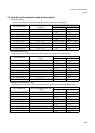
■ Clock division
The clocks used to drive the internal operation of the device allow division ratios relative to the base clock to
be set independently for each clock. This function allows the optimum operating frequency to be selected for
each circuit.
The division ratios are set in the operating clock division setting registers (DIVR0 and DIVR1). These registers
contain 4-bit settings that specify the ratio for each clock. The division ratio relative to the base clock =
(register value+1). The duty ratio is always 50, even if an odd numbered division ratio is set.
If a setting is modified, the new setting applies from the next rising edge of the clock.
The division ratio settings are not initialized by an operation reset (RST) and the settings from before the reset
are maintained. The ratio settings are only initialized by a settings initialization reset (INIT). When changing
the clock source from its initial setting to a high speed clock, always set the division ratio first.
Device operation is not guaranteed if the result of the clock source selection, main PLL multiplier setting, and
division ratio setting is a frequency that is higher than the maximum permitted frequency. Please take care
with these settings. (In particular, take care with the sequence in which you change clock source settings.)