631
Chapter 32 USART (LIN / FIFO)
4.USART Registers
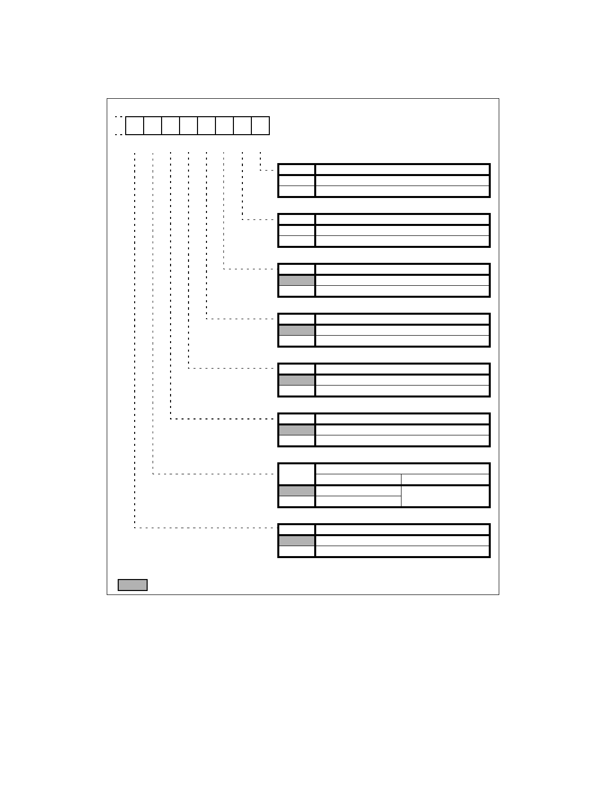
Figure 4-6 Configuration of the Extended Communication Control Register (ECCR04)
Initial value
0 0 0 0 0 0 X X
B
W R/W R/W R/WR/W R R
bit0
TBI * Transmission bus idle
0 Transmission is ongoing
1 no transmission activity
bit1
RBI * Reception bus idle
0 Reception is ongoing
1 no reception activity
bit2
BIE * Bus idle interrupt enable
0 disable Bus idle interrupt
1 enable Bus idle interrupt
bit3
SSM Synchronous start/stop bits in mode 2
0 No start/stop bits in synchronous mode 2
1 Enable start/stop bits in synchronous mode 2
bit4
SCDE Serial Clock Delay enable in mode 2
0 disable clock delay
1 enable clock delay
bit5
MS Master / Slave function in mode 2
0 Master mode (generating serial clock)
1 Slave mode (receiving external serial clock)
bit6
LBR
Set LIN break
write read
0 ignored
always read 0
1 Generate LIN break
bit7
INV Invert Serial Data
0 Serial data is not inverted (NRZ format)
1 Serial data is inverted (RZ format)
* not useable in mode 2
R/W : Readable and writable
R : Flag is read only
W : Flag is write only
X : Indeterminate
: Initial value
76543210
R/W


