


542
Chapter 31 External Bus
3.Setting Example of the Chip Select Area
3. Setting Example of the Chip Select Area
In the external bus interface, a total of eight chip select areas can be set.
This section presents an example of setting the chip select area.
■ Example of Setting the Chip Select Area
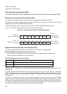
The address space of each area can be placed, in units of a minimum of 64 KB, anywhere in the 4 GB space
using ASR0-7 (Area Select Registers) and ACR0-7 (Area Configuration Registers). When bus access is made to
an area specified by these registers, the corresponding chip select signals (CS0-CS7) are activated (L output)
during the access cycle.
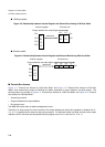
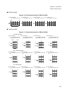
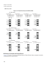
● Example of setting ASRs and ASZ3-0
• ASR1=0003
H
ACR1 ASZ3-0=0000
B
: Chip select area 1 is assigned to 00030000
H
to 0003FFFF
H
.
• ASR2=0FFC
H
ACR2 ASZ3-0=0010
B
: Chip select area 2 is assigned to 0FFC0000
H
to 10000000
H
.
• ASR3=0011
H
ACR3 SZ3-0=0100
B
: Chip select area 3 is assigned to 00100000
H
to 00200000
H
.
Since at this point 1 MB is set for bits ASZ3-0 of the ACR, the unit for boundaries 1 MB and bits 19-16 of ASR3
are ignored. Before there is any writing to ACR0 after a reset, 00000000
H
-FFFFFFFF
H
is assigned to chip select
area 0.
Set the chip select areas so that there is no overlap.
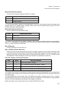
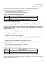
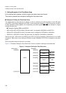
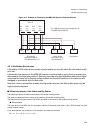
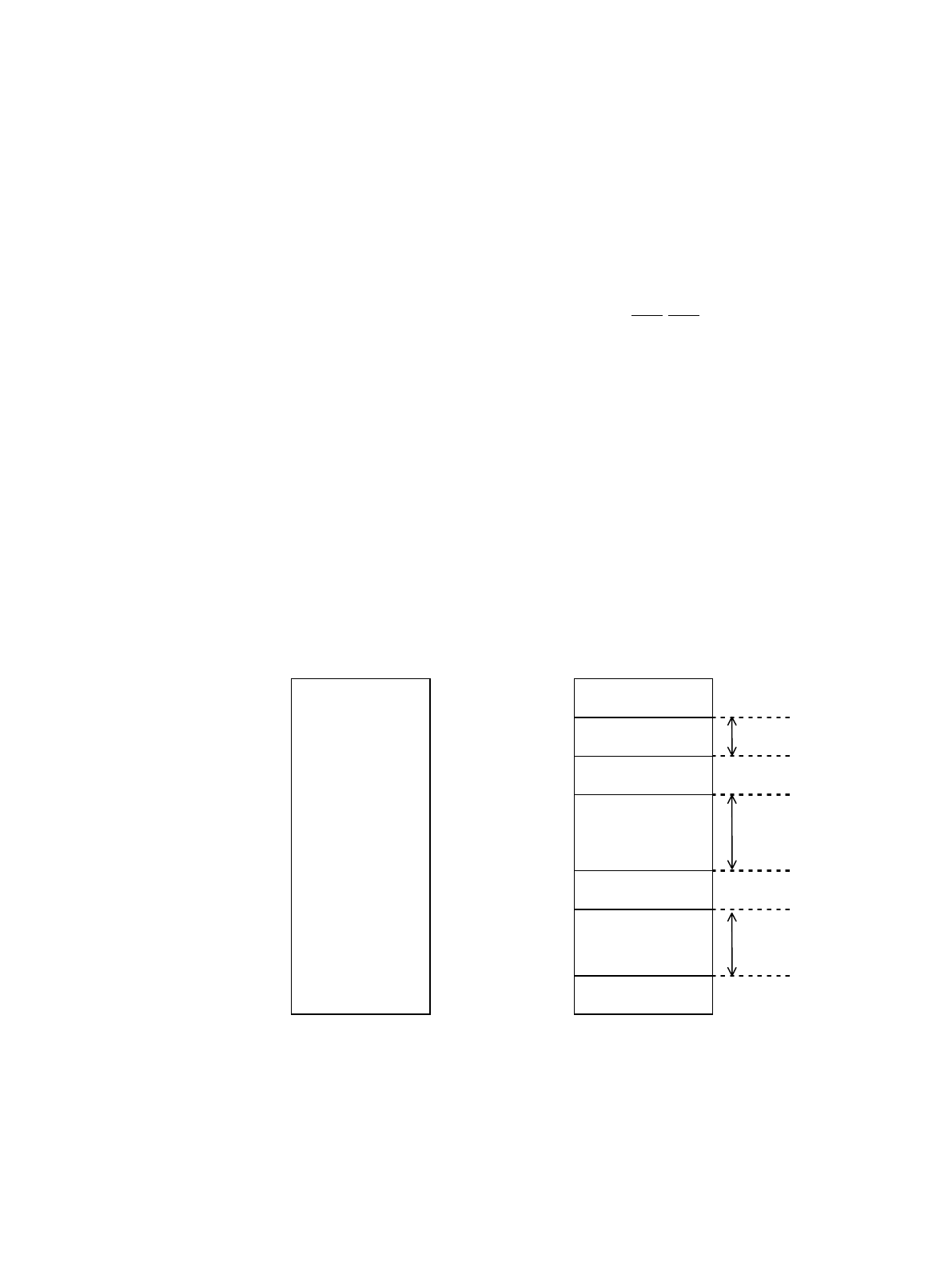
Figure 3-1 "Example of Setting the Chip Select Area" shows an example of setting the chip select area.
Figure 3-1 Example of Setting the Chip Select Area
(Initial value) (Example)
00000000
H
00000000
H
00030000
H
Area 1 64 KB
00040000
H
Area 0 00100000
H
Area 3 1 MB
00200000
H
0FFC0000
H
0FFFFFFF
H
Area 2 256 KB
FFFFFFFF
H
FFFFFFFF
H