850
Chapter 41 Up/Down Counter
5.Operation
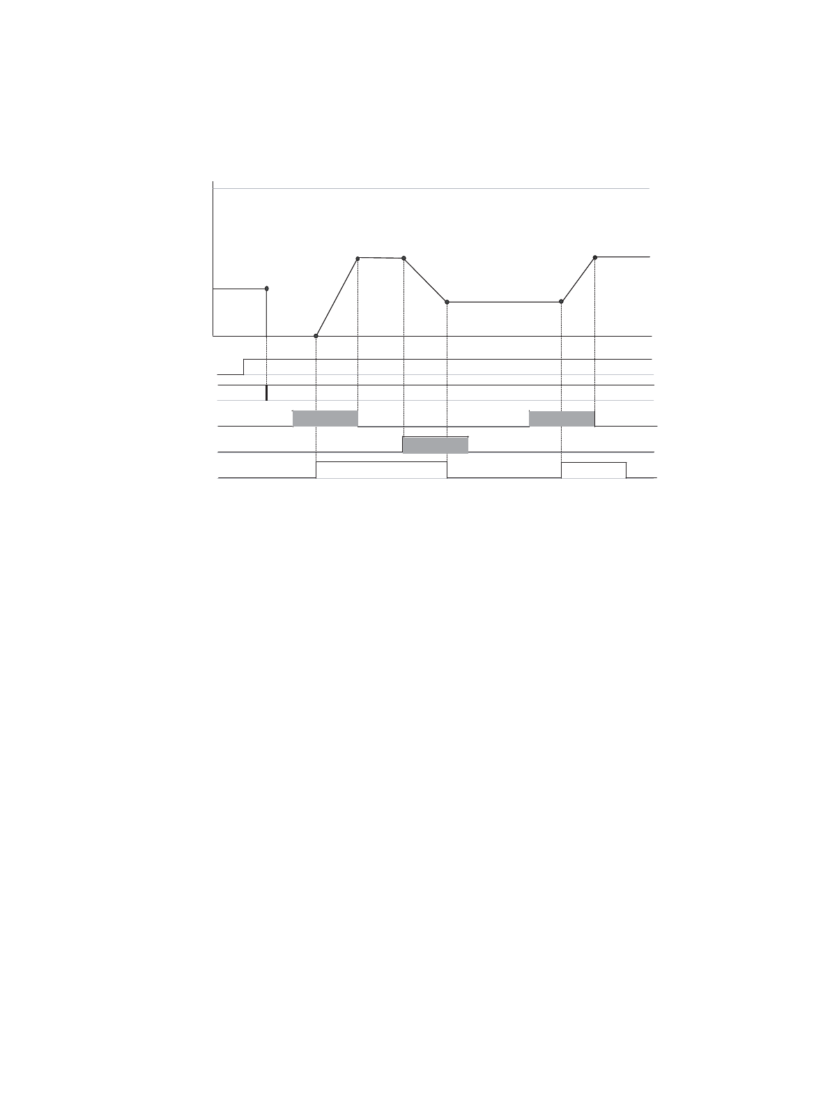
5.3 Up/Down Count Mode CMS[1:0]=“01”
Countgate at the ZIN pin
(1) Appropriate bits (Counting enable CSTR, Reload enable RLDE and Clear enable UCRE) are set.
(2) Up/Down Counter is cleared. (“0” is written to CGSC).
(3) Neither pulse input to the AIN pin nor counting at the ZIN pin being enabled, Up/Down Counter neither
counts up nor down.
(4) Counting is enabled at the ZIN pin.
(5) Up/Down Counter counts up.
(6) When pulse input to the AIN pin stops, Up/Down Counter stops counting.
(7) When a pulse input to the BIN pin is detected, Up/Down Counter counts down.
(8) When counting is disabled at the ZIN pin, Up/Down Counter stops counting.
(9) Neither pulse input to the AIN pin nor counting at the ZIN pin being enabled, Up/Down Counter neither
counts up nor down.
(10) Counting is enabled at the ZIN pin.
(11) Up/Down Counter counts up.
(12) When pulse input to the AIN pin stops, Up/Down Counter stops counting.
(13) Counting is disabled at the ZIN pin.
ZIN=Gate control
CSTR, RLDE, UCRE
UDCC
AIN
BIN
ZIN (Gate)
CGE[1:0]=“10”
“H”“H”
(1)
(8)
(7)
(7)
(6)
(6)
(4)
(3)
(2)
(2)
(10)
(9)
(8)
(11)
(12)
(12)
(13)


