


343
Chapter 26 DMA Controller
2.DMA Controller (DMAC) Registers
completed.
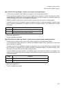
When DMA transfer is started, data in this register is stored in the counter buffer of the DMA-dedicated transfer
counter and is decremented by 1 (subtraction) after each transfer unit. When DMA transfer is completed, the
contents of the counter buffer are written back to this register and then DMA ends. Thus, the transfer count value
during DMA operation cannot be read.
• When reset: Not initialized.
• These bits are readable and writable. Always access DTC using halfword length or word length.
• During reading, the count value is read. The reload value cannot be read.
2.2 Control/Status Registers B (DMACB0 to 4)
Control/status registers B (DMACB0 to 4) control the operation of each DMAC channel and exist
independently for each channel.
This section describes the configuration of control/status registers B (DMACB0 to 4) and their
functions.
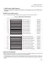
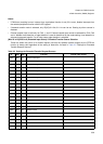
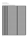
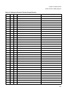
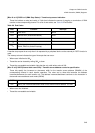
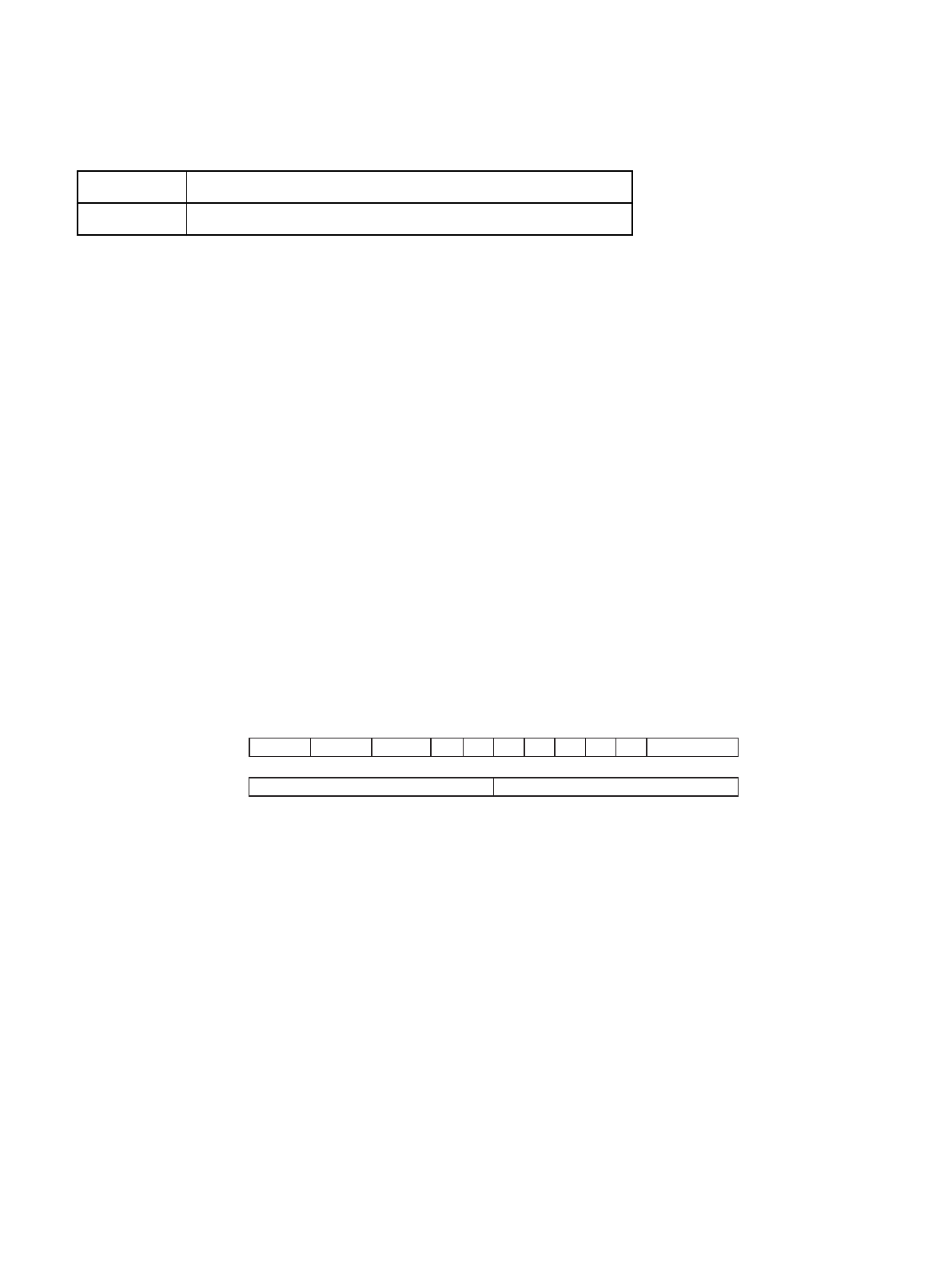
■ Bit Configuration of Control/Status Register B (DMACB0 to 4)
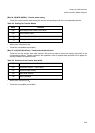
Figure 2-3"Bit Configuration of Control/Status Registers B (DMACB0 to 4)" shows the bit configuration of control/
status registers B (DMACB0 to 4).
Figure 2-3 Bit Configuration of Control/Status Registers B (DMACB0 to 4)
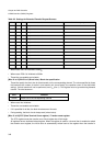
■ Detailed Bit of Control/Status Register B (DMACB0 to 4)
The following describeds the functions of the bits of control status register B (DMACB0 to 4).
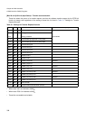
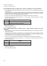
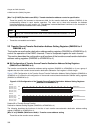
[Bits 31 to 30] TYPE (TYPE)*: Transfer type setting
These bits are the transfer type setting bits and set the type of operation for the corresponding channel.
• 2-cycle transfer mode: In this mode, the transfer source address (DMASA) and transfer destination address
(DMADA) are set and transfer is performed by repeating the read operation and write operation for the number
of times specified by the transfer count. All areas can be specified as a transfer source or transfer destination
(32-bit address).
• Fly-by transfer mode: In this mode, external <--> external transfer is performed in one cycle by setting a
memory address as the transfer destination address (DMADA). Be sure to specify an external area for the
DTC Function
XXXX
B
Transfer count for the corresponding channel
bit
31 30 29 28 27 26 25 24 23 22 21 20 19 18 17 16
bit
1514131211109876543210
TYPE[1:0]
DADM ERIE EDIE
DSS[2:0]
DADRSADRDTCR
SADM
WS[1:0]MOD[1:0]
SASZ[7:0] DASZ[7:0]
Address 000204
H
(ch0)
00020C
H
(ch1)
000214
H
(ch2)
00021C
H
(ch3)
000224
H
(ch4)
XXXXXXXXXXXXXXXX
B
Initial value
0000000000000000