


878
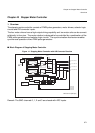
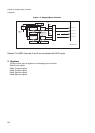
Chapter 43 Stepper Motor Controller
2.Registers
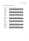
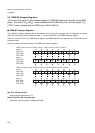
2.4 PWM1&2 Selection Registers
The PWM1&2 selection registers determine whether to set the output of the external pin of the
stepping motor controller to "0", "1", PWM pulse or high impedance.
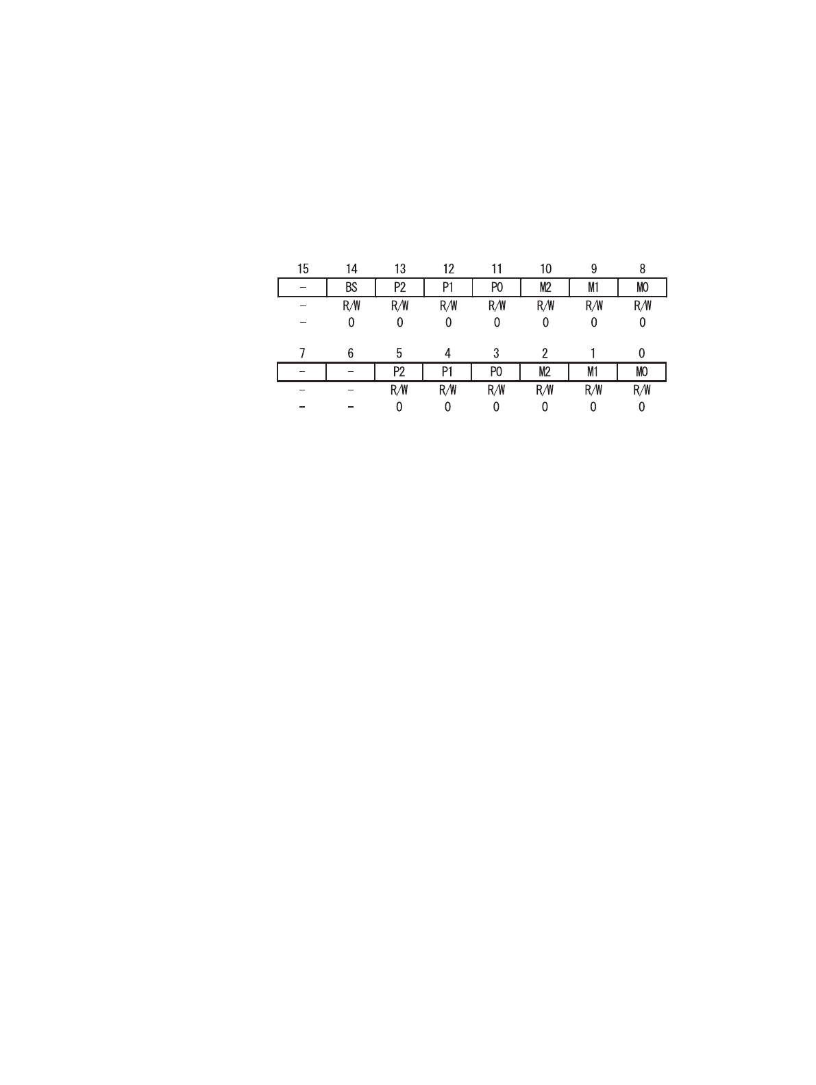
■ PWM1&2 Selection Registers
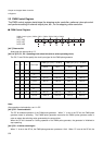
[bit 15] Reserved bit
Always set the reserved bit to "0".
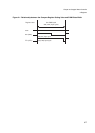
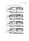
[bit 14] BS: Rewrite bit
The BS bit makes the setting for the PWM output match another setting. Until the BS bit is set, changes made
to the two compare registers and two selection registers are not reflected in the output signal.
When "1" is set to the BS bit, the PWM pulse generator and the selector load the values of the registers at the
end of the current PWM cycle. The BS bit is cleared to “0” automatically at the beginning of the next PWM
cycle.
When "1" is set to the BS bit and is being cleared automatically by software simultaneously, the BS bit is set to
“1” (no change is made to the BS bit) and the automatic clearing is cancelled.
When "0" is set to the BS bit and is being cleared automatically by software simultaneously, the BS bit is
cleared to “0”, however the PWM pulse generator and the selector are not load the values of the registers at
the end of the current PWM cycle.
Note:
When the BS bit equals “1” when executing a read-modify-write type instruction the BS bit is "1" read as “1”
and wrote as "1" in the BS bit again.
When the BS bit was cleared automatically by the starting of a PWM cycle in between read and write, "1" is
set after BS bit has cleared again.
Therefore, values of the registers are loaded in the PWM pulse generator and selector when the BS bit is not
set to "1" by the end of the next PWM cycle.
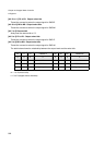
PWM2 Selection register (PWS20, PWS21, PWS22, PWS23, PWS24, PWS25)
Address
Address
PWM1 Selection register (PWS10, PWS11, PWS12, PWS13, PWS14, PWS15)
0x096, 0x09E
0x0A6, 0x0AE
0x0B6, 0x0BE
0x097, 0x09F
0x0A7, 0x0AF
0x0B7, 0x0BF