


956
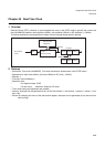
Chapter 49 Real-Time Clock
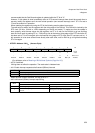
5.Operation
5. Operation
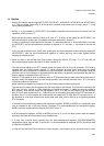
This section describes Real-time Clock operation.
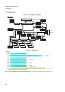
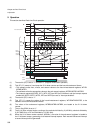
(1) The start bit (ST) is set to “1” and then “0”. (Register initialization operation)
(2) This (ST=“0”) resets to 0 and stops the 21 bit down counter and the hour/minute/second timers.
(3) • The software writes hour, minute, and second values to the hour/minute/second registers, WTHR/
WTMR/WTSR.
• The software writes the appropriate values to the sub-second registers, WTBR0/WTBR1/WTBR2.
• The interrupt request bits (INT0, INT1, INT2, INT3 and INT4) are initialized, and the interrupt request
enable bits (INTE0, INTE1, INTE2, INT3 and INTE4) are set to “interrupts enabled”.
(4) The start bit (ST) is set to “1”.
(5) This (ST=“1”) causes the values of the hour/minute/second registers, WTHR/WTMR/WTSR, to be
loaded to the hour/minute/second timers.
(6) The values of the sub-second registers, WTBR0/WTBR1/WTBR2, are loaded to the 21 bit down
counter.
(7) The run flag (RUN) is set to “1”.
(8) The 21 bit down counter begins counting at the mainclock divided by 2 (4/2 MHz), subclock divided by
2 (32.768/2 KHz) or RC clock divided by 2 (100/2 kHz).
(9) When the 21 bit down counter reaches “000000
H
”, the value of the sub-second registers is loaded to
the 21 bit down counter, generating a half-second interrupt request. Each second half-second interrupt
a second interrupt will be generated.
(1)
(7)
(8)
(2)
(2)
(11)
21 bit down counter
0000 h
59M
Minute
Hour
23H
Second
59S
Clear
ST
WTSR
WTMR
WTHR
STOP
RUN
Clear
Clear
Clear
(
S
M
H
(2)
(2)
(5)
(4)
(3)
(11)
(10)
(9)
(5)
(5)
(6)
(10)
(12)
(19)
(20)
(20)
(20)
(20)
(20)
(17)
(3)
WTBR(0-2)
(1)
(7)
(8)
(2)
(2)
(11)
0000 h
59M
23H
reload value
59S
ST
S
M
H
Hour/
Minute/
Second
counters
(2)
(2)
(5)
(4)
(3) Hour/Minute/Second register values
(11)
(10)
(9)
(5)
(5)
(6)
(10)
(12)
(19)
(20)
(20)
(20)
(20)
(20)
(17)
(3) Sub-second values
(14)
Other circuits are stopped
Half
Second