


210
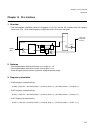
Chapter 14 PLL Interface
4.Registers
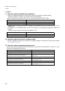
• PLLMULG: Address 048Fh (Access: Byte, Halfword, Word)
(See “Meaning of Bit Attribute Symbols (Page No.10)” for details of the attributes.)
• Bit7-6: Reserved bitThe read value is always “0”.
• Bit5-0: PLL auto gear divide-by-G step multiplier selection
(Note) See chapter 6. Clock Auto Gear Up/Down for detailed information on how to use this function.
(Note) The register value can not be changed once PLL is selected as clock source (CLKS[1:0]=”10”).
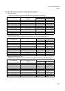
• PLLCTRL: Address 0490h (Access: Byte, Halfword, Word)
(See “Meaning of Bit Attribute Symbols (Page No.10)” for details of the attributes.)
• Bit7-4: Reserved bitThe read value is always “0”.
• Bit3: Interrupt Enable Gear DOWN.
• Bit2: Interrupt Flag Gear DOWN.
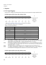
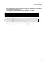
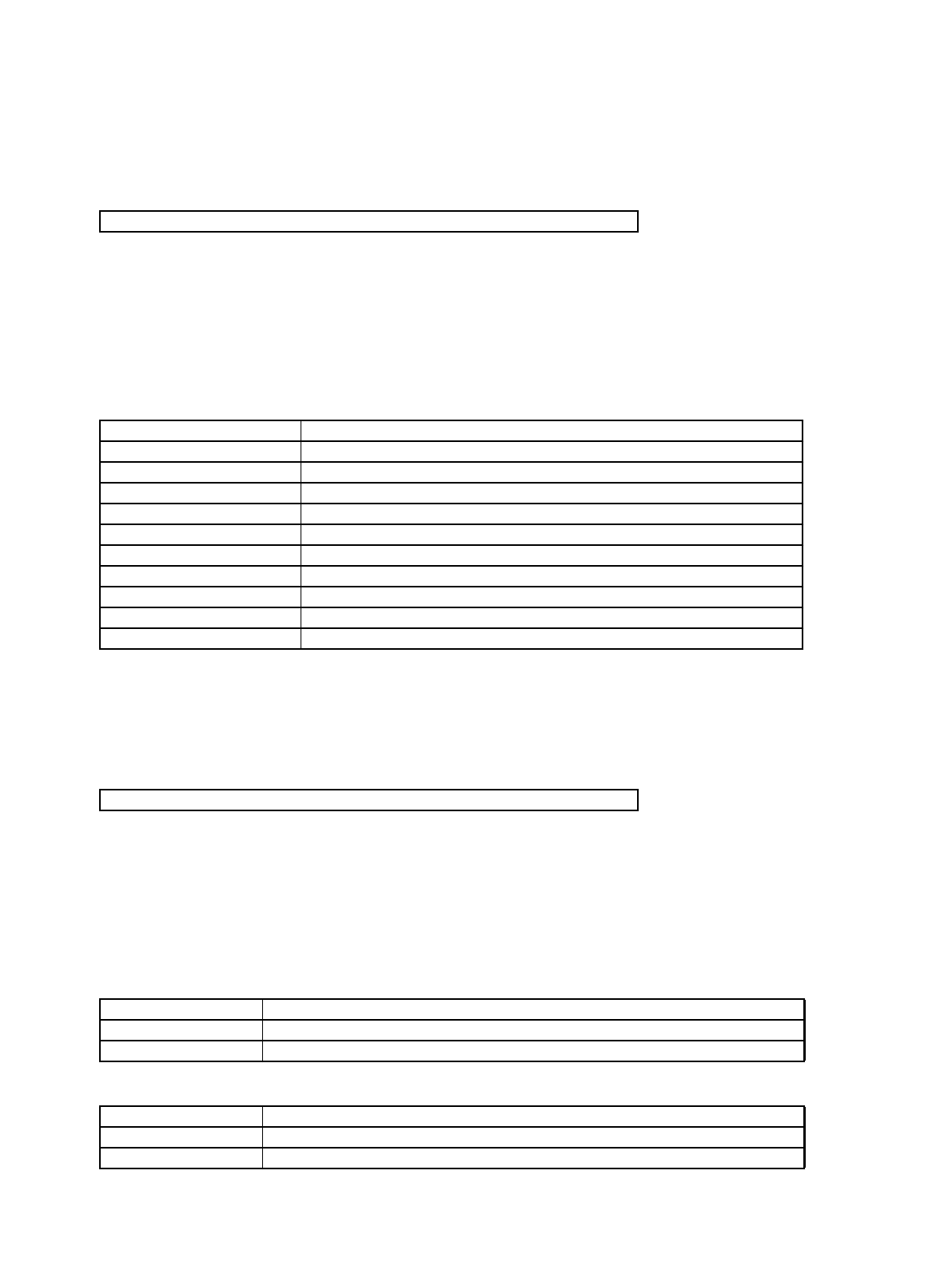
76543210 bit
MLG7 MLG6 MLG5 MLG4 MLG3 MLG2 MLG1 MLG0
00000000
Initial value (
INIT pininput,
watchdog reset)
XXXXXXXX
Initial value
(Software reset)
R/W R/W R/W R/W R/W R/W R/W R/W Attribute
MLG5-MLG0 Divide-by-G step multiplier
00000000 Divide-by-G step x 1 (multiply by 1)
00000001 Divide-by-G step x 2 (multiply by 2)
00000010 Divide-by-G step x 3 (multiply by 3)
00000011 Divide-by-G step x 4 (multiply by 4)
00000100 Divide-by-G step x 5 (multiply by 5)
00000101 Divide-by-G step x 6 (multiply by 6)
00000110 Divide-by-G step x 7 (multiply by 7)
00000111 Divide-by-G step x 8 (multiply by 8)
...... .....
11111111 Divide-by-G step x 256 (multiply by 256)
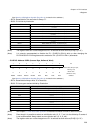
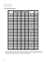
76543210 bit
- - - - IEDN GRDN IEUP GRUP
00000000
Initial value (
INIT pininput,
watchdog reset)
0000XXXX
Initial value
(Software reset)
R/W R/W R/W R/W R/W RM1/W R/W RM1/W Attribute
IEDN Function
0 Gear DOWN interrupt disabled [Initial value]
1 Gear DOWN interrupt enabled
GRDN Function
0 Gear DOWN interrupt not active [Initial value]
1 Gear DOWN interrupt active