


436
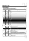
Chapter 30 I/O Ports
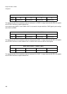
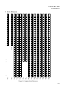
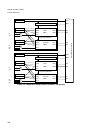
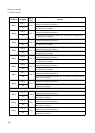
1.I/O Ports Functions
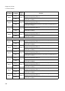
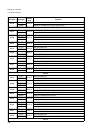
P06_7
P06_7
TP04_0
General purpose I/O. This function is enabled in the single-chip mode or by
setting the corresponding PFR to ‘0’.
A15
I/O pin for bit 15 of the external address bus. This function is enabled when
the external bus is enabled.
P06_6
P06_6
TP04_0
General purpose I/O. This function is enabled in the single-chip mode or by
setting the corresponding PFR to ‘0’.
A14
I/O pin for bit 14 of the external address bus. This function is enabled when
the external bus is enabled.
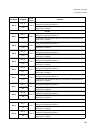
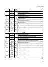
P06_5
P06_5
TP04_0
General purpose I/O. This function is enabled in the single-chip mode or by
setting the corresponding PFR to ‘0’.
A13
I/O pin for bit 13 of the external address bus. This function is enabled when
the external bus is enabled.
P06_4
P06_4
TP04_0
General purpose I/O. This function is enabled in the single-chip mode or by
setting the corresponding PFR to ‘0’.
A12
I/O pin for bit 12 of the external address bus. This function is enabled when
the external bus is enabled.
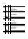
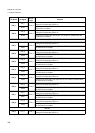
P06_3
P06_3
TP04_0
General purpose I/O. This function is enabled in the single-chip mode or by
setting the corresponding PFR to ‘0’.
A11
I/O pin for bit 11 of the external address bus. This function is enabled when
the external bus is enabled.
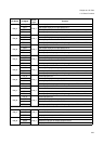
P06_2
P06_2
TP04_0
General purpose I/O. This function is enabled in the single-chip mode or by
setting the corresponding PFR to ‘0’.
A10
I/O pin for bit 10 of the external address bus. This function is enabled when
the external bus is enabled.
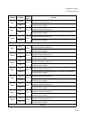
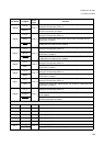
P06_1
P06_1
TP04_0
General purpose I/O. This function is enabled in the single-chip mode or by
setting the corresponding PFR to ‘0’.
A9
I/O pin for bit 9 of the external address bus. This function is enabled when the
external bus is enabled.
P06_0
P06_0
TP04_0
General purpose I/O. This function is enabled in the single-chip mode or by
setting the corresponding PFR to ‘0’.
A8
I/O pin for bit 8 of the external address bus. This function is enabled when the
external bus is enabled.
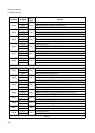
Port 07
P07_7
P07_7
TP04_0
General purpose I/O. This function is enabled in the single-chip mode or by
setting the corresponding PFR to ‘0’.
A7
I/O pin for bit 7 of the external address bus. This function is enabled when the
external bus is enabled.
P07_6
P07_6
TP04_0
General purpose I/O. This function is enabled in the single-chip mode or by
setting the corresponding PFR to ‘0’.
A6
I/O pin for bit 6 of the external address bus. This function is enabled when the
external bus is enabled.
P07_5
P07_5
TP04_0
General purpose I/O. This function is enabled in the single-chip mode or by
setting the corresponding PFR to ‘0’.
A5
I/O pin for bit 5 of the external address bus. This function is enabled when the
external bus is enabled.
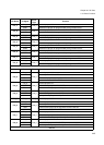
Pin Name I/O Signal
Circuit
Type
Function