


251
Chapter 18 Timebase Counter
4.Registers
4. Registers
4.1 STCR: Standby Control Register
Controls transition to standby modes, pin states during stop mode, whether to halt the clock during stop mode,
the oscillation stabilization wait time, and software reset.
Note: See also “Chapter 10 Standby (Page No.155)” and “Chapter 20 Software Watchdog Timer (Page
No.273)” chapters.
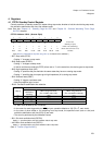
• STCR: Address 0481h (Access: Byte)
(See “Meaning of Bit Attribute Symbols (Page No.10)” for details of the attributes.)
• Bit7: Stop mode (STOP)
• Setting “1” changes to stop mode.
• Bit6: Sleep mode (SLEEP)
• Setting “1” changes to sleep mode.
• If this bit and the stop mode bit (STOP) bit are set to “1” at the same time, the device goes to stop mode.
• Bit5: High impedance mode (HIZ)
• Setting “0” specifies that pins maintain the same states they have on entering stop mode.
• Setting “1” specifies that pin outputs go to high impedance (Hi-z) during stop mode.
• Bit4: Software reset (SRST)
• Setting “0” triggers a software reset.
• Note that negative logic is used.
• Bit3-2: Oscillation stabilization time selection
• F2: Main clock divided by two or subclock
• In the case of a reset triggered by an INIT pin input, operation defaults to “00” (F2 x 2
1
, main clock).
• In the case of other resets or on recovering from stop mode, the specified clock (main or sub) and
oscillation stabilization wait time (OS[1:0]) are used.
• The count is performed by the timebase counter.
• Bit1: Sub clock oscillation halt (OSCD2)
Setting “1” specifies that the sub clock oscillation halts in stop mode.
• bit0: Main clock oscillation halt (OSCD1)
Setting “1” specifies that the main clock oscillation halts in stop mode.
(See “8. Caution (Page No.262)”.)
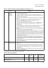
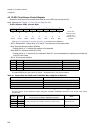
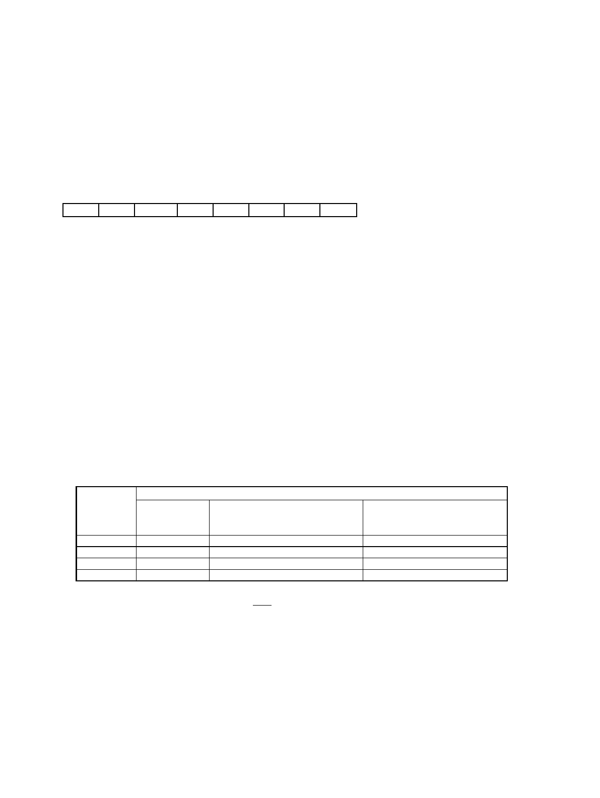
7 6 5 4 3 2 1 0 bit
STOP SLEEP HIZ SRST OS1 OS0 OSCD2 OSCD1
00 1 10011
Initial value
(INITX pin input)
0 0 1 1 X X 1 1 Initial value (Watchdog)
0 0 X 1 X X X X Initial value (Software reset)
R/W R/W R/W R1,W R/W R/W RX,W R/W Attribute
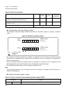
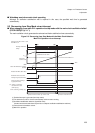
OS[1:0]
The oscillation stabilization wait time after a reset (INIT) or on recovering from stop mode.
Oscillation
stabilization
wait time
When using main clock
(For a 4.0MHz main clock)
When using subclock
(For a 32.768kHz subclock)
00
Φ2 × 2
1
1.00µs61µs
01
Φ2 × 2
11
1.0ms 62.5ms
10
Φ2 × 2
16
32ms 2.0s
11
Φ2 × 2
22
2s 128s