879
Chapter 43 Stepper Motor Controller
2.Registers
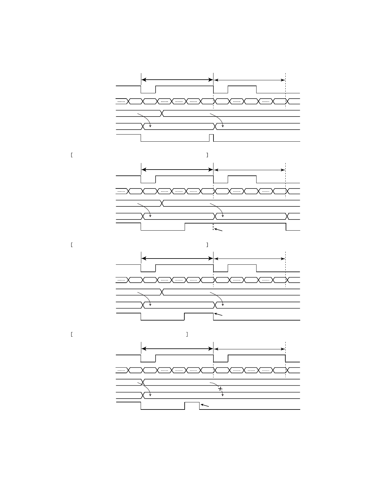
Figure 2-2 load timing of PWM compare register value
Automatic clear and "1" simultaneously
write of a BS bit.
000h3FFh 3FFh 000h 200h 3FFh 000h
PWM 1 cycle
XXXh 200h
Load the values of the registers and
reflected in the output signal.
3FFh
3FFh 200h
Load Load
When set a BS bit in "1" with automatic clear simultaneously
000h3FFh 3FFh 000h 200h 3FFh 000h
Automatic clear and "0" simultaneously
write of a BS bit.
PWM 1 cycle
XXXh 200h
Load the values of the registers
and reflected in the output signal.
3FFh
3FFh 200h
Load Load
When set a BS bit in "0" with automatic clear simultaneously
BS
000h3FFh 3FFh 000h 200h 3FFh 000h
PWM 1 cycle
PWM pulse
PWM pulse generator
compare register value
PWM pulse generator
counter value
XXXh 200h
Load the values of the registers and
reflected in the output signal.
3FFh
PWM compare
register value
BS
PWM pulse
PWM pulse generator
compare register value
PWM pulse generator
counter value
PWM compare
register value
BS
PWM pulse
PWM pulse generator
compare register value
PWM pulse generator
counter value
PWM compare
register value
BS
PWM pulse
PWM pulse generator
compare register value
PWM pulse generator
counter value
PWM compare
register value
3FFh 200h
Load Load
[Automatic clear of BS bit]
"0" write of a BS bit before the 1 cycle end.
000h3FFh 3FFh 000h 3FFh 000h
PWM 1 cycle
XXXh
Not load the values of the registers and
not reflected in the output signal.
3FFh
3FFh 200h
Load
Not load
When set a BS bit in "0" before the PWM cycle end


