


135
Chapter 8 Device State Transition
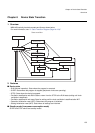
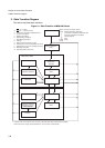
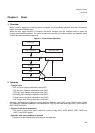
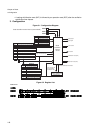
3.State Transition Diagram
3.1 RUN (Normal Operation)
This is the state where program is executed with all clocks and all circuits are enabled.
This state has various paths for a state transition. However, if the synchronous reset mode is selected the
state transition operations for some requests are different from normal reset mode. For more information, see
the chapter of “Chapter 9 Reset (Page No.139)”.
3.2 SLEEP
This is the state where only the CPU's program execution is stopped and the peripheral circuits are operating.
Embedded memories and internal/external buses are stopped unless the DMA controller requests them. This
state is entered by program operation.
• Upon generation of valid interrupt requests the SLEEP state is cancelled and the RUN mode (Normal
operation) is entered.
• Upon generation of the setting-initialization reset request by the external INITX pin the setting-initialization
reset state (INIT) is entered.
• Upon generation of the operation-initialization reset request (external RSTX or software reset) the
operation-initialization reset state (RST) is entered.
3.3 STOP
All internal circuits are stopped, all internal clocks and the PLL is stopped. Main/Sub oscillation and RC
oscillation (which can be connected to the Real Time Clock (RTC) can be stopped by setting the related
registers). This state is entered by program operation.
Additionally high impedance for external pins can be enabled by setting the related register.
• Upon generation of specific valid interrupt requests (requiring no clock), active oscillation timer interrupt or
main clock oscillation stabilization timer interrupt request the oscillation stabilization wait RUN state is entered.
• Upon generation of the setting-initialization reset request by the external INITX pin the setting-initialization
reset state (INIT) is entered.
• Upon generation of the operation-initialization reset request (external RSTX or software reset) the
operation-initialization reset state (RST) is entered.
The Real Time Clock (RTC) can be supplied in the STOP mode with either main or sub oscillation clock, if the
control bits for oscillation disable (OSCDx of the STCR register) are not set to disable.
The Real Time Clock (RTC) can be supplied in the STOP mode with the RC oscillation clock, if the control bit
for oscillation enable (RCE of the CSVCR register) is not set to disable.
3.4 Oscillation-stabilization-wait RUN
All internal circuits are stopped except for clock generation control parts (timebase counter and device state
control parts). All internal clocks are stopped while oscillation circuits and enabled main PLL is operated. This
state is entered automatically after the return from STOP.
• High-impedance control of external pins by STOP is cancelled.
• After the configured oscillation-stabilization-wait time has passed the RUN (Normal operation) state is
entered.
• Upon generation of the setting-initialization reset request by the external INITX pin the setting-initialization
reset state (INIT) is entered.
• Upon generation of the operation-initialization reset request (external RSTX or software reset) the
operation-initialization reset state (RST) is entered.