274
Chapter 20 Software Watchdog Timer
3.Configuration
3. Configuration
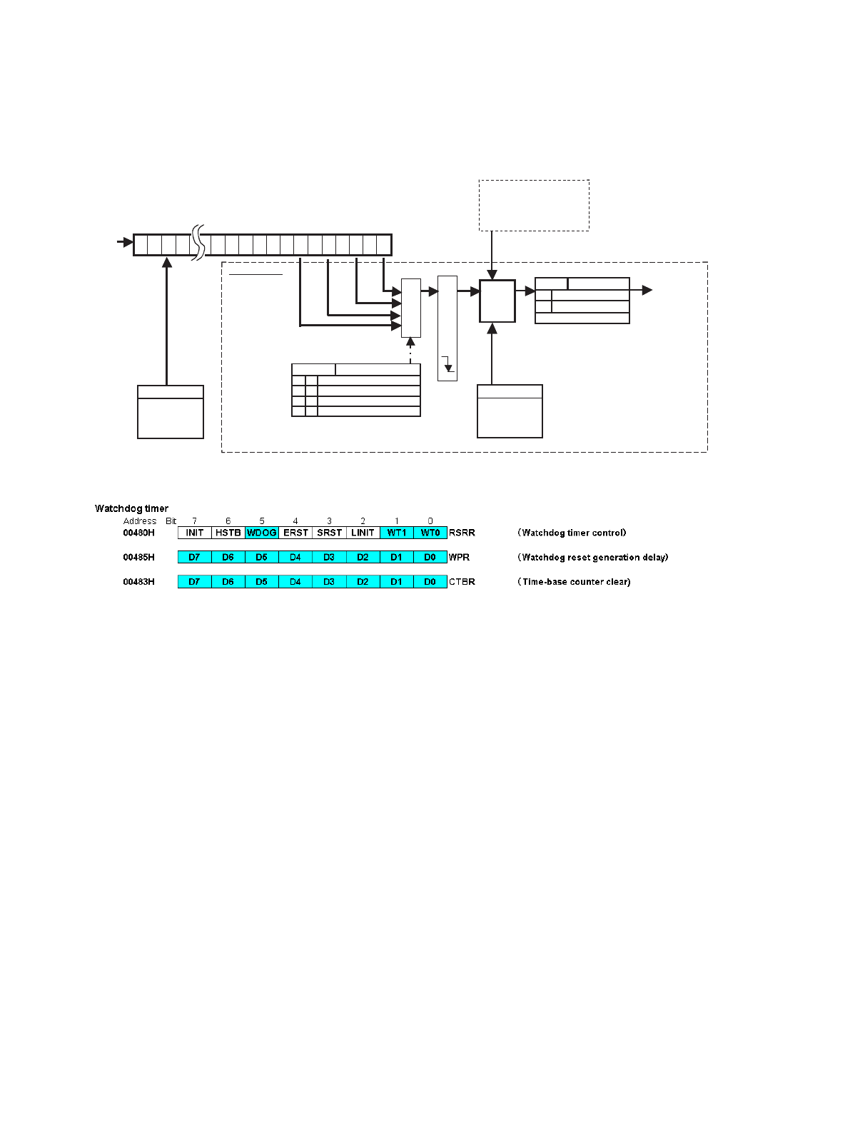
Figure 3-1 Configuration Diagram
Figure 3-2 List of Registers
Timebase counter
Base clock
(φ)
CTBR
Timer clear
2
1
2
2
2
3
2
4
2
14
2
15
2
16
2
17
2
18
2
19
2
20
2
21
2
22
2
23
2
24
2
25
2
26
0123 13141516171819202122232425
Selector
Edge detection
WIF OSCR:bit 7
0
1
Without interrupt request
With interrupt request
WRITE; 0: Flag clear
1-bit
counter
WT1-WT0
2
20
0
0
1
10
11
0
2
22
2
24
2
26
WPR
To the reset
circuit
Watchdog timer
-Sleep
-Stop
-Oscillation stability
wait RUN
(26-bit counter)
CTBR
Clears the counter
after writing “A5h”
and then “5Ah”.
Clears the counter
after writing “A5h”
and then “5Ah”.
WIF
0
1
For watchdog detection
Watchdog reset
RSRR:bit2-1
0
0
1
10
11
0
φ
x
φ x
φ x
φ x
WPR
Temporary stop


