


938
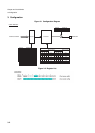
Chapter 47 LCD Controller
7.Q&A
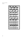
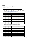
7.4 How do I set a duty cycle?
Use the display mode select bit (LCR0.MS[1:0]).
The display mode select bit also serves as an operation start/stop control bit.
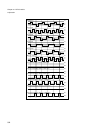
7.5 How do I control starting and stopping of LCD?
Use the display mode select bit (LCR0. MS[1:0]) to control start and stop of operation.
See (4).
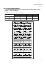
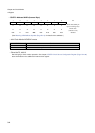
7.6 How do I enable or disable LCD display?
Use either of the following methods:
• Use the blanking select bit (LCR0. BK).
• The LCD display can be blanked by using the display mode select bit (LCR0. MS[1:0]) to select LCD
deactivation.
7.7 How do I enable LCD display even in the sub-stop mode?
Use the sub-stop operation enable bit (LCR0. LCEN).
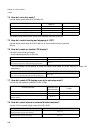
7.8 How do I select internal or external divided resistors?
Use the LCD drive power supply control bit (LCR0. VSEL).
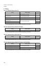
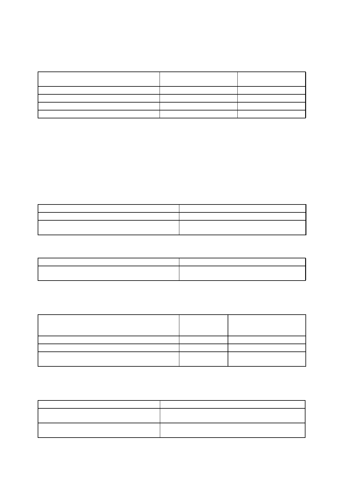
Controlled operation
Display mode select bit
(MS[1:0])
N (Time division number)
To deactivate LCD (Pin output: “L”) Set to “00”. N/A
To set the 1/2 duty cycle output mode Set to “01”. 2
To set the 1/3 duty cycle output mode Set to “10”. 3
To set the 1/4 duty cycle output mode Set to “11”. 4
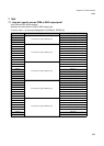
Controlled operation Blanking select bit (BK)
To enable LCD display Set to “0”.
To disable (blank) LCD display
(Non-selected waveform is output through segment pins.)
Set to “1”.
Controlled operation Display mode select bit (MS[1:0])
To deactivate LCD
(A “L” level is output through common and segment pins.)
Set to “00”.
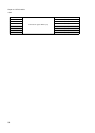
Controlled operation
Frame period
generation clock
select bit (CSS)
Sub-stop operation enable bit
(LCEN)
To disable LCD display during sub-stop – Set to “0”.
To enable LCD display during sub-stop Set to “1”. Set to “1”.
To enable LCD display when the main clock stops and the
subclock operates
Set to “1”. –
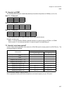
Controlled operation LCD drive power supply control bit (VSEL).
To use external divided resistors
(Internal divided resistors disconnected)
Set to “0”.
To use internal divided resistors
(Internal divided resistors connected)
Set to “1”.