


821
Chapter 39 Programmable Pulse Generator
8.Caution
8. Caution
• If the Interrupt Request flag (PCN.IRQF) equals “1” and the Interrupt Request flag is set to “0” at the same
time, the setting of the Interrupt Request flag to “1” overrides the flag clear request.
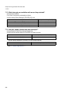
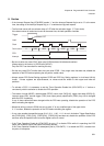
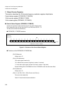
• The first load comes with a maximum delay of 2.5T after the activation trigger. (T: Count clock)
If the down counter is loaded and counts at the same time, the load operation overrides.
• Be sure to write duty value PDUT after cycle PCSR has been initialized and rewritten.
(Always write in the order of (1)PCSR and (2)PDUT.)
Only the PDUT can be written for rewriting the duty.
• Set the duty value PDUT smaller than the cycle value PCSR. If any larger value has been set, disable the
operation of the PPG before replacing the duty with a smaller value.
• Always access PPG Period Setting registers PCSR and PPG Duty Setting registers in a half-word (16-bit)
format. If these registers are byte-accessed, no values would be written to their upper and lower bit
positions.
• To activate a PPG, it is necessary to set the Timer Operation Enable bits (PCN.CNTE) to “1” before or
concurrently with the activation to enable the PPG operation.
• The values of mode (MDSE), restart enable (RTRG), count clock (CKS[1:0]), trigger input edge (EGS[1:0]),
interrupt cause (IRS), internal trigger (TSEL) and output polarity specification (OSEL) may not be changed
while the PPG is operating.
If any of these values has been changed while the PPG was operating, disable the operation of the PPG
before reloading the register.
• Whenever writing a value to GCN2, be sure to write “0” to any undefined part of the upper 4 bits.
If “1” is written, disable the operation of the PPG before reloading the register.
• If any value outside the specified range (0110, 0111, 1100 - 1111) is set in Activation Trigger Specification
bits (TSEL0[3:0]), (TSEL1[3:0]), (TSEL2[3:0]), (TSEL3[3:0]) has been set, disable the operation of the PPG
and then write the specified value to let the register return to normal.
• If the Timer Operation Enable bit (PCN.CNTE) is set to “0” to disable PPGn while it is operating, the PPG
stops, with its status (count and output level) being latched.
If the Timer Operation Enable bit is subsequently set to (PCN.CNTE) “1” to enable the PPG, it restarts from
the point of interruption.
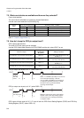
Trigger
Load
Maximum 2.5T
Clock
Count value
X 0003 0002 0001 0000 0003 0002
PPG
Interrupt
Effective edge Duty match Counter borrow