


717
Chapter 34 CAN Controller
2.Register Description
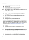
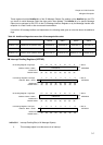
These registers hold the NewDat bits of the 32 Message Objects. By reading out the NewDat bits, the CPU
can check for which Message Object the data portion was updated. The NewDat bit of a specific Message
Object can be set/reset by the CPU via the IFx Message Interface Registers or by the Message Handler after
reception of a Data Frame or after a successful transmission.
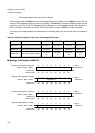
If more than 32 message buffers are implemented, the following table gives an overview about the additional
flags:
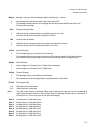
Table 2-2 Additional flags when more than 32 message buffers exist
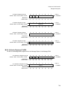
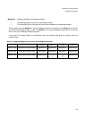
■ Interrupt Pending Registers (INTPND)
addr+0 addr+1 addr+2 addr+3
NEWDT 4 & 3 NewDat 64-33 (address 0x94) NewDat64-57 NewDat56-49 NewDat48-41 NewDat40-33
NEWDT 6 & 5 NewDat 96-65 (address 0x98) NewDat96-89 NewDat88-81 NewDat80-73 NewDat72-65
NEWDT 8 & 7 NewDat 128-97 (address 0x9C) NewDat128-121 NewDat120-113 NewDat112-105 NewDat104-97
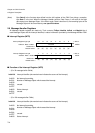
IntPnd32-1 Interrupt Pending Bits (of all Message Objects)
0 This message object is not the source of an interrupt.
IntPnd32-25
⇐ Bit no.
Read/write ⇒
(R) (R) (R) (R) (R) (R) (R) (R)
Default value⇒
(0) (0) (0) (0) (0) (0) (0) (0)
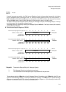
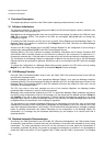
Int Pending Register 2 high byte
Address : Base + 0xA0
H
15 14 13 12 11 10 9 8
INTPND2H
IntPnd24-17
⇐ Bit no.
Read/write ⇒
(R) (R) (R) (R) (R) (R) (R) (R)
Default value⇒
(0) (0) (0) (0) (0) (0) (0) (0)
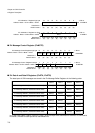
Address :
Base + 0x
A1H
765432 10
INTPND2L
Int Pending Register 2 low byte
IntPnd16-9
⇐ Bit no.
Read/write ⇒
(R) (R) (R) (R) (R) (R) (R) (R)
Default value⇒
(0) (0) (0) (0) (0) (0) (0) (0)
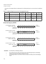
Int Pending Register 1 high byte
Address : Base + 0xA2
H
15 14 13 12 11 10 9 8
INTPND1H
IntPnd8-1
⇐ Bit no.
Read/write ⇒
(R) (R) (R) (R) (R) (R) (R) (R)
Default value⇒
(0) (0) (0) (0) (0) (0) (0) (0)
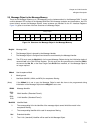
Address :
Base + 0x
A3H
765432 10
INTPND1L
Int Pending Register 1 low byte