


643
Chapter 32 USART (LIN / FIFO)
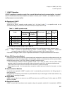
6.USART Baud Rates
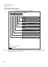
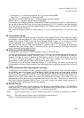
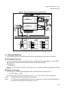
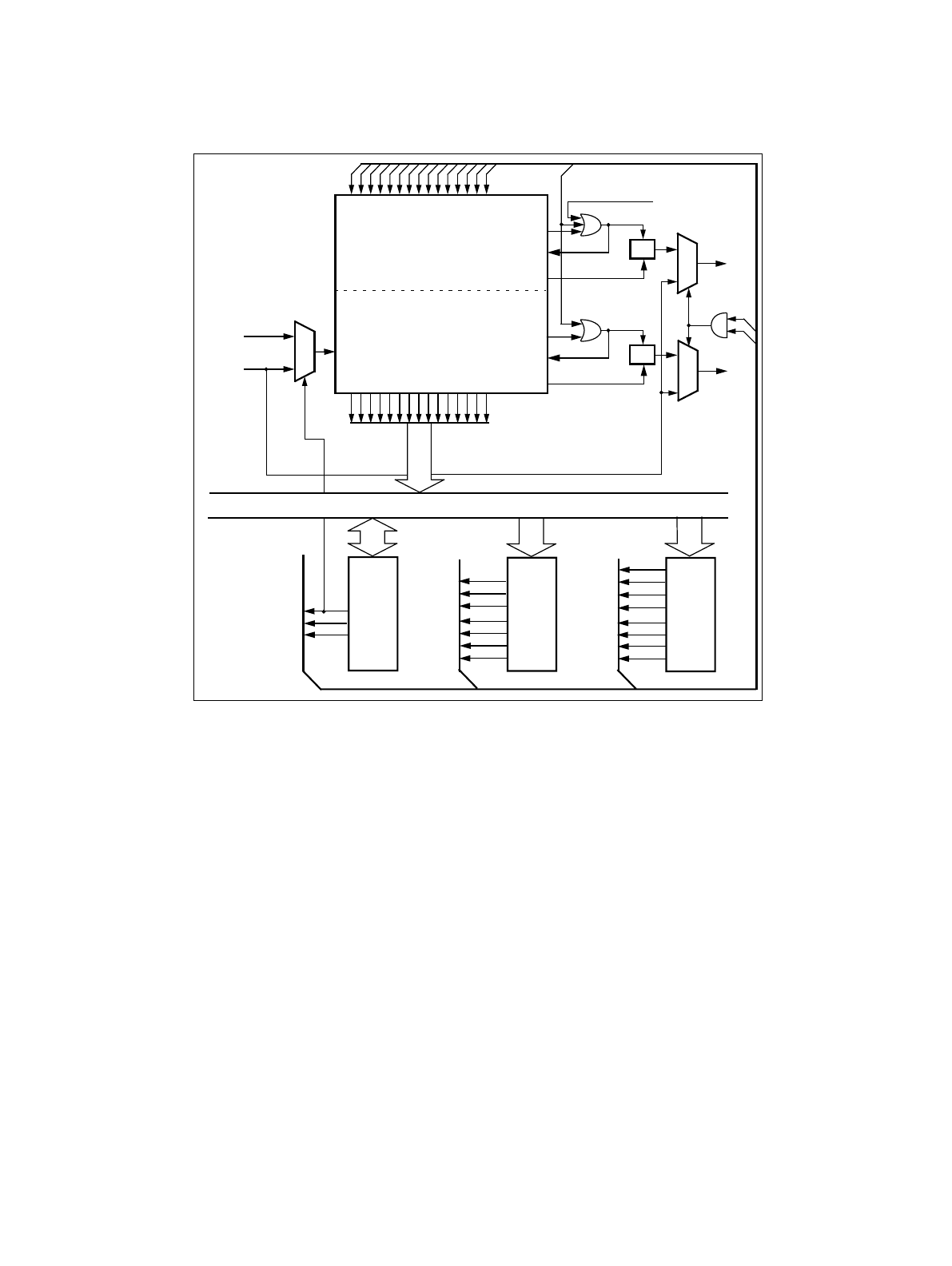
Figure 6-1 Baud rate selection circuit (reload counter)
6.1 Setting the Baud Rate
This section describes how the baud rates are set and the resulting serial clock frequency is calculated.
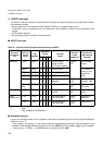
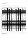
■ Calculating the baud rate
The both 15-bit Reload Counters are programmed by the Baud Rate Generator Registers 1 and 0 (BGR14,
04). The following calculation formula should be used to set the wanted baud rate:
Reload Value:
v = [F / b] - 1 ,
where F is the resource clock (CLKP), b the baud rate and [ ] gaussian brackets (mathematical rounding
function).
■ Example of Calculation
If the CPU clock is 16 MHz and the desired baud rate is 19200 baud then the reload value v is:
v = [16
*
10
6
/ 19200] - 1 = 832
The exact baud rate can then be recalculated: b
exact
= F / (v + 1), here it is: 16
*
10
6
/ 833 = 19207.6831
(Note) Setting the reload value to 0 stops the reload counter.
(Note) The minimum recommended division ratio is 4 (i.e. reload value is 3) due to RX oversampling filter in
asynchronous communication modes (mode 0,1 and 3).
Internal data bus
EXT
REST
BGR14
register
BGR04
register
BGR7
BGR10
BGR9
BGR8
BGR6
BGR5
BGR4
BGR3
BGR2
BGR1
BGR0
16-bit Reload Counter
Txc = 0?
Txc = v/2?
Reload
Count Value: Txc
Reload Value: v
REST
(external
set
reset
clock
OTO
1
0
1
0
BGR13
BGR12
BGR11
BGR14
Transmission
16-bit Reload Counter
Reception
FF
Rxc = 0?
Rxc = v/2?
Reload
set
reset
FF
EXT
OTO
1
0
Reload Value: v
Start bit falling
Reception
Clock
Transmission
Clock
CLK
input)
SMR04
register
SCK04
edge detected