


379
Chapter 26 DMA Controller
6.DMA External Interface
6. DMA External Interface
This section provides operation timing charts for the DMA external interface.
■ DMA External Interface Pins
DMA channels 0-3 have the following DMA-dedicated pins (DREQ, DACK, and DEOP):
• DREQ: DMA transfer request input pin for demand transfer. A transfer is requested with an input.
• DACK: This pin becomes active (L output) when DMA accesses an external area via the external interface.
• DEOP: This pin becomes active (L output) in synchronization with the last access to complete DMA transfer.
• IORD: This signal becomes active when the direction I/O -> memory is selected for fly-by transfer.
• IOWR: This signal becomes active when the direction memory -> I/O is selected for fly-by transfer.
Note:
Refer to 4.10 "DMA Access Operation" for the operation example of DMA external interface.
6.1 Input Timing of the DREQx Pin
The DREQx pin is a DMA start request signal. If the pin is also used as a port, enable the DREQ
input using the PFR register. This section shows the input timing of the DREQx pin.
■ Timing of Transfer Other Than Demand Transfer
For transfer other than demand transfer, set the DMA start source to edge detection. Although there is no rule for
rise/fall timing, use three or more clock cycles as the holding time the DREQ signal. To make another transfer
request, enter the request after the DMA transfer is completed (make a request after DEOP is output).
If a request is made before DEOP is output, it may be ignored.
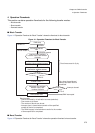
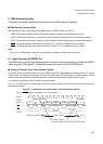
Figure 6-1"Timing Chart for Transfer Other Than the Demand Transfer" shows the timing chart for transfer other
than demand transfer.
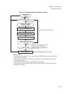
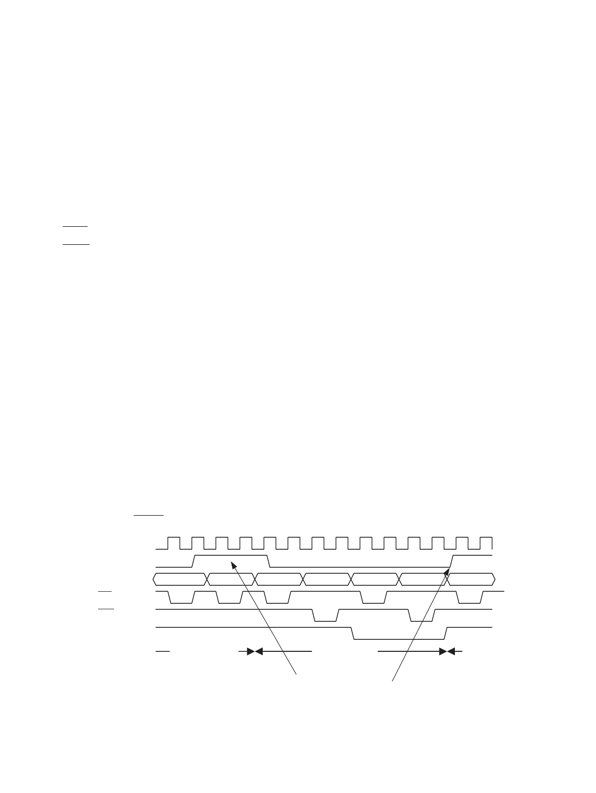
Figure 6-1 Timing Chart for Transfer Other Than the Demand Transfer
When a DREQ edge is requested (for 2-cycle transfer)
MCLK
DREQ
A24 to 0 #RD1 #WR1 #RD2 #WR2
RD
WR
DEOP
DMA transfer CPU
3 or more cycles
The next request must be after DEOP output
CPU operation