


651
Chapter 32 USART (LIN / FIFO)
7.USART Operation
SPI). This will make sure, that the transmission data is valid and stable at any falling clock edge. (Necessary, if
the receiving device samples the data at falling clock edge). This function is disabled when CCO is enabled.
If the Serial Clock Edge Select (SCES) bit of the ESCR is set, the USARTs clock is inverted and thus samples
the reception data at the falling clock edge. In this case, the sending device must make sure that the serial
data is valid at the falling serial clock edge.
When both the SCES and the SCDE bit are set, data is stable at the rising clock edge, as in the case of SCES
= SCDE = 0. However, the marker value for idle state is inverted (low).
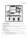
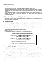
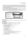
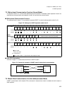
If the CCO bit of the Extended Status/Control Register (ESCR5) is set, the serial clock on the SCK5 pin in
master mode is continuously clocked out. It is strongly recommended to use start and stop bits in this mode to
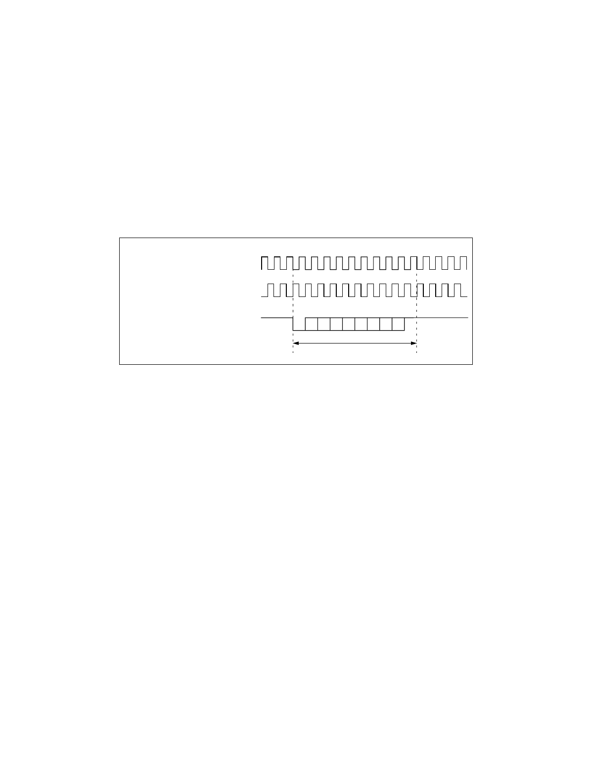
signalize the receiver, when a data frame begins and when it stops. Figure 7-5 illustrates this.
Figure 7-5 Continuous clock output in mode 2
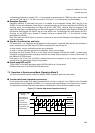
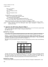
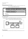
■ Data signal mode
NRZ data format is selected, if ECCR04: INV = 0, otherwise the signal mode for the serial data input and
output pin is RZ.
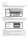
■ Error Detection
If no Start/Stop bits are selected (ECCR04: SSM = 0) only overrun errors are detected.
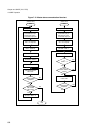
■ Communication
For initialization of the synchronous mode, the following settings have to be made:
• Baud Rate Generator Registers (BGR0/1):
Set the desired reload value for the dedicated Baud Rate Reload Counter
• Serial Mode Control Register (SMR04):
• MD1, MD0: "10b" (Mode 2)
• SCKE:“1” for dedicated Baud Rate Reload Counter
“0” for external clock input
• SOE:“1” for transmission and reception
“0” for reception only
• Serial Control Register (SCR04):
• RXE, TXE: one of these flag bit is set to "1"
• PEN: no parity provided - Value: don’t care
• P, SBL, A/D: no parity, no stop bit(s), no Address/Data selection - Value: don’t care
• CL: automatically fixed to 8-bit data - Value: don’t care
• CRE: "1" (the error flag is cleared for initialization, possible transmission
or reception will cut off)
• Serial Status Register (SSR04):
data frame
reception or transmission clock
data stream (SSM = 1)
(here: no parity, 1 stop bit)
ST
SP
(SCES = 0, CCO = 1):
reception or transmission clock
(SCES = 1, CCO = 1):