


519
Chapter 31 External Bus
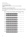
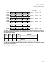
2.External Bus Interface Registers
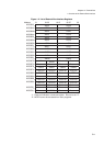
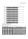
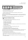
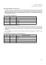
Set the access type as the combination of all bits.
For details of the operations of each access type, see the explanation of operation of each type.
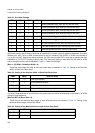
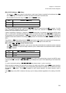
● CS area mask setting function
If you want to set an area some of whose operation settings are changed for a certain CS area (referred to as the
base setting area), you can set TYPE3-0 of ARC in another CS area to 1111 so that the area can function as a
mask setting area.
If you do not use the mask setting function, disable any overlapping area settings for multiple CS areas.
Access operations to the mask setting area are as follows:
• CS corresponding to a mask setting area is not asserted.
• CS corresponding to a base setting area is not asserted.
• For the following ACR settings, the settings on the mask setting area side are valid:
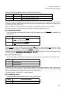
• Bits 11-10 (DBW1-0): Bus width setting
• Bits 9-8 (BST1-0): Burst length setting
• Bit 7 (SREN): Sharing-enable setting
• Bit 6 (PFEN): Prefetch-enable setting
• Bit 5 (WREN): Write-enable setting (For this setting only, only a setting that is the same as that of the base
setting area is allowed)
• Bit 4 (LEND): Little endian setting
• For the following ACR setting, the setting on the base setting area side is valid:
• Bits 3-0 (TYPE3-0): Access type setting
• For the AWR settings, the settings on the mask setting area side are valid.
• For the CHER settings, the settings on the mask setting area side are valid.
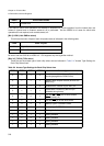
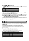
A mask setting area can be set for only part of another CS area (base setting area). You cannot set a mask
setting area for an area without a base setting area. Use care when setting ASR and bits ASZ3-0 of ACR.
The following restrictions apply when using these bits:
• A write-enable setting cannot be implemented by a mask.
• Write-enable settings in the base CS area and the mask setting area must be identical.
• If write operations to a mask setting area are disabled, the area is not masked and operates as a base CS
area.
• If write operations to the base CS area are disabled but are enabled to the mask setting area, the area has no
base, resulting in malfunctions.
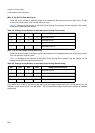
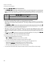
1111
Mask area setting (The access type is the
same as that of the overlapping area)
*3
*1: If this setting is made, WR0-WR3 can be used as the enable of each bit.
*2: Only the ACR6 and ACR7 registers are valid. The ACR0, ACR1, ACR2, ACR3, ACR4,
and ACR5 registers are disabled.
*3: See the CS area mask setting function (next bullet).
Table 2-4 Access Type Settings for Each Chip Select Area
TYP3 TYP2 TYP1 TYP0 Access type