


297
Chapter 22 Main Oscillation Stabilisation Timer
8.Caution
8. Caution
• To wait until the main clock oscillation stability is attained while the subclock is in operation, it is necessary
to acquire wait time using the main clock oscillation stability wait timer.
(An unstable clock may be supplied to the entire device, and normal operation is not guaranteed if the MCU
operation mode is switched from the sub-RUN to the main RUN mode without waiting until the main clock
oscillation becomes stable.)
• The value for the oscillation stability wait time is an estimated value because the oscillation period of the
main clock oscillation is unstable for the beginning immediately after the oscillation has started.
• If the main clock oscillation stops, the main clock oscillation stability wait interrupt (interval interrupt) is not
generated either because the main clock oscillation stability wait timer stops. The main clock oscillation
should be enabled for processing that uses the main clock oscillation stability wait interrupt (interval
interrupt).
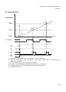
• The flag is set to “1” (flag setting preference) if the timer interrupt request (WIF=“1”) and the writing
operation where “0” is written by software in the flag occur simultaneously.
• The main clock oscillation stability wait timer is counted up with the main clock. As a result, in the following
state, the counting of the timer used to stop the main clock oscillation also stops.
• If the timer operation enable bit (OSCRH.WEN) is “0”, the timer stops counting.
• If the main clock is stopped in the stop mode (STCR.OSCD1=“1”), the timer stops counting from the
moment the stop mode is activated.
• If the main clock oscillation is stopped (OSCCR.OSCDS1=“1”) during subclock operation, the timer stops
while the subclock is in operation.
• If you want to enable (WIE=“1”) the interrupt request after the reset is released, and the interval time to be
modified, be sure to simultaneously set the interrupt request flag (WIF) and the clear bit (WCL) to “0”
beforehand.
• The timer interrupt request bit (WIF), timer interrupt request enable bit (WIE), timer enable bit (WEN) and
timer clear bit (WCL) are initialized using the setting initialization reset (INIT terminal input, watchdog reset).
• Be sure to set the interval selection bit (WS[1:0]) after startup (after setting initialization reset) by the
software.
• The main clock oscillation stability wait timer control register should be initialized (to set the initial value) only
with the setting initialization reset (INIT terminal input, watchdog reset) because the software reset does not
initialize the register and the current value is held.
• If the counter clear (WPCR.WCL=“0”) and the overflow for the selected bit occur simultaneously, the
interrupt request flag (WIF) is not set to “1”.