


181
Chapter 12 Instruction Cache
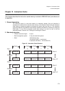
2.Main body structure
FLUSHbit is set to "0" when the cache is flushed.)
[Bit 1] LRU bit (way 1 only)
This bit exists only in the instruction cache tag in way 1. The bit indicates way 1 or 2 as the
way containing the last entry accessed in the selected set. When set to "1", the LRU bit
indicates that the entry of the set in way 1 is the last entry accessed. When set to "0", it
indicates that the one in way 2 is the last entry accessed.
[Bit 0] ETLK: Entry lock bit
This bit is used to lock all the entries in the block corresponding to the tag in the cache. When
set to "1", the entries are locked and are not updated when a cache miss occurs. Note,
however, that invalid sub-blocks are updated. If a cache miss occurs with both of ways 1 and
2 in the entry lock states, access to external memory takes place after losing one cycle used
for evaluating the cache miss.
● Control register structure
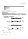
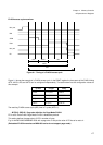
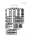
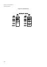
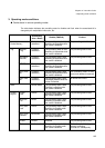
ISIZE [bits 1 to 0] : SIZE1 and SIZE0
These bits set the cache capacity. The combination of the settings determines the cache size,
IRAM size, and the address map in RAM mode as shown in Figure I-CACHE-3. When the
cache size is changed, be sure to flush the cache and release the entry lock before turning on
the cache.
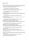
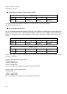
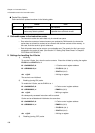
ICHCR [bits 7 to 0] :
The ICHCR (I-Cache Control Register) controls the operation of the instruction cache. Writing
a value to the ICHCR has no effect on the caching of any instruction fetched within three
cycles that follow.
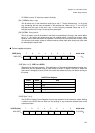
ISIZE (8 bit) 76543210Initial value
0000 03C7
H
- - - - - - SIZE1 SIZE0
---- --10
B
- - - - - - R/W R/W
CACHE Size Register
SIZE1 SIZE0 Size
0 0 1 KB
0 1 2 KB
1 0 4 KB (initial value)
1 1 Setting disabled
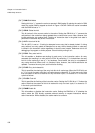
ICHCR (8 bit) 765432 1 0Initial value
0000 03E7
H
RAM - GBLK ALFL EOLK ELKR FLUSH ENAB
0-00 0000
B
R/W - R/W R/W R/W R/W R/W R/W