


114
Chapter 5 CPU Registers
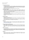
2.Dedicated Registers
2.1 PC: Program Counter
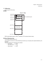
Program Counter (PC) consists of 32 bits.
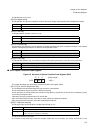
Figure 2-2 Bit Structure of Program Counter (PC)
Program counter (PC) indicates active instruction address.
Upon the execution of the instruction, program counter (PC)’s bit 0 is cleared.
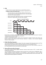
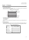
2.2 PS: Program Status Register
Program status register (PS) is the register to hold program status which consists of three parts including ILM, SCR
and CCR.
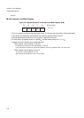
All undefined bits are reserved bit. Upon the reading, “0” is always read. Writing is invalid.
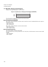
Program status register (PS) consists of condition code register (CCR), system condition code register (SCR) and
interrupt level mask register (ILM).
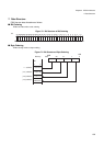
Figure 2-3 Bit Structure of Program Status (PS)
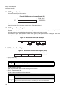
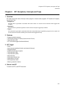
■ CCR: Condition Code Register
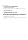
Figure 2-4 Structure of Condition Code Register (CCR)
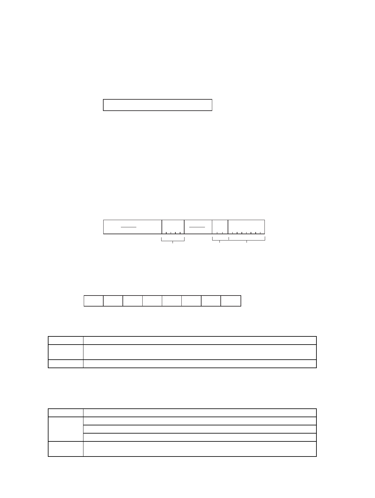
• [Bit 5] S: Stack flag
This bit specifies stack pointer.
This bit becomes “0” by reset.
After using R15 as USP, write “0” before executing RETI instruction.
• [Bit 4] I: Interrupt-enable flag
This bit enables and disables user interrupt request.
S Description
0
Uses R15 as SSP. Upon generating EIT, this bit automatically becomes “0”.
(Note that the value saved in stack is the value before clear.)
1 Uses R15 as USP.
I Description
0
Disables user interrupt.
Upon executing INT instruction, this bit becomes “0”.
(Note that the value saved in stack is the value before clear.)
1
Enables user interrupt.
Mask processing of user interrupt request is controlled by the value which is held in ILM.
31
[Initial value]
PC XXXXXXXX
H
0
31 20 16
10 8 7 0
bit
ILM
SCR
CCR
7
6
5
4
3
120
bit
-
-
S
I
N
Z
V
C
--00XXXX
B
Initial value