


818
Chapter 39 Programmable Pulse Generator
7.Q & A
7.10 How do I generate an activation trigger?
Generating a trigger
Methods of generating an activation trigger are described below.
• Activating a software trigger
Use the Software Trigger bit (PCN.STGR) to set.
Write “1” to the Software Trigger bit (STGR) to generate an activation trigger.
Always functional, regardless of the internal trigger.
• Activating PPGs with reload timers
The reload timers need to be set up and activated. For more information, see “Chapter 38 Reload Timer (Page
No.775)”.
An activation trigger is generated when the edge specified by the reload timer output signal is generated with the
reload timer underflow.
• Activating PPGs with external triggers
An activation trigger is generated when the edge specified on the specified pin appears. There is no need for
configuration of the port registers; the trigger is always connected to the PPGs.
• Activating a PPG with the EN trigger input bits (GCN2.EN0) - (GCN2.EN3)
An activation trigger can be generated by rewriting the level of the EN trigger input bits (GCN2.EN0) - (GCN2.EN3).
• Activating multiple PPGs concurrently
The same trigger (trigger input bit) can be specified with the PPG trigger specification bits to activate all the PPGs
simultaneously when the trigger is generated.
• Even if an activation trigger is generated before the operation of a PPG is enabled, that PPG would not be
activated. Be sure to enable the operation of a PPG before generating a trigger to activate it. (See “7.2 How
do I enable or disable PPG operations? (Page No.813)”.)
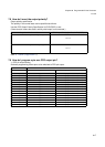
7.11 How do I stop a PPG operation?
PPG stop bit setting (See “7.2 How do I enable or disable PPG operations? (Page No.813)”.)
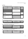
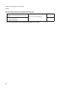
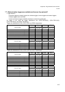
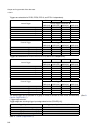
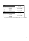
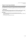
7.12 What interrupt registers are used?
PPG interrupt vector, PPG interrupt level setting
The table below summarizes the relationships among the PPG number, interrupt level and interrupt vector.
For more information about the interrupt levels and interrupt vectors, see “Chapter 24 Interrupt Control (Page
No.311)”.
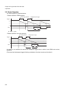
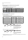
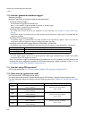
Edge
Software-Based Setting Procedure (EN0, EN1, EN2, EN3)
Rising edge First, set the EN bit to “0”, then the EN bit to “1”.
Falling edge First, set the EN bit to “1”, then to “0”.
Interrupt Vector (Default) Interrupt Level Setting Bit (ICR[4:0])
PPG0
#112
Address: 0FFE3Ch
Interrupt Level register (ICR48)
Address: 0470h
PPG1
#113
Address: 0FFE38h
PPG2
#114
Address: 0FFE34h
Interrupt Level register (ICR49)
Address: 0471h
PPG3
#115
Address: 0FFE30h
PPG4
#116
Address: 0FFE2Ch
Interrupt Level register (ICR50)
Address: 0472h
PPG5
#117
Address: 0FFE28h