157
Chapter 10 Standby
4.Registers
4. Registers
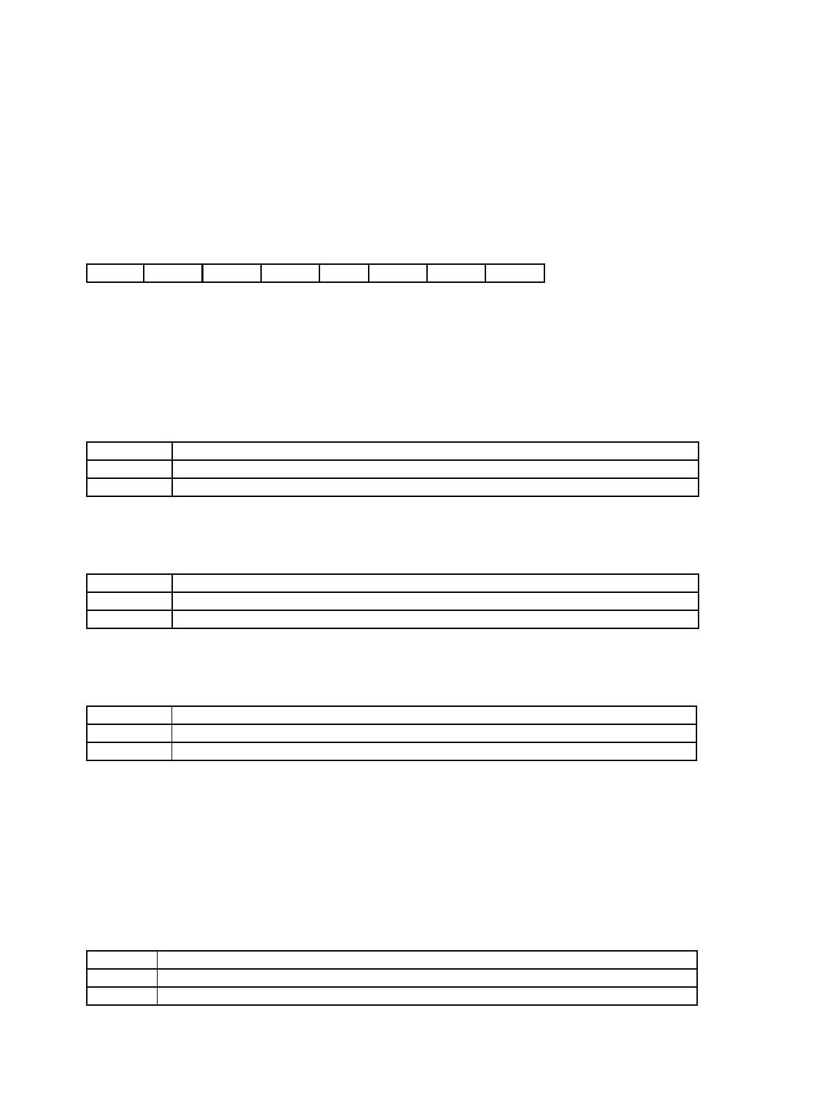
4.1 STCR: Standby Control Register
Used to control transition to the stop and sleep standby modes, and to specify the pin states and whether to
halt the oscillation during stop mode.
Note: See “Chapter 9 Reset (Page No.139)” also.
• STCR: Address 0481h (Access: Byte)
(See “Meaning of Bit Attribute Symbols (Page No.10)” for details of the attributes.)
• Bit7: Stop mode
• Goes to “0” when a reset (INIT pin input or software reset) occurs or on recovery from stop mode.
• Going directly from main PLL operation to stop mode is prohibited. (See “8. Caution (Page No.165)”.)
• Bit6: Sleep mode
• If this bit and the stop mode bit (STOP) bit are set to “1” at the same time, the device goes to stop mode.
• Goes to “0” when a reset (INIT pin input or software reset) occurs or on recovery from sleep mode.
• Bit5: High impedance mode
• The default setting is high impedance.
• Bit4: Software reset (SRST)
• Setting this bit to “0” invokes a software reset.
• Bit3-2: Oscillation stabilization time selection (OS[1:0])
• Setting these bits in the range “00”-“11” sets the oscillation stabilization time to use after recovering from
stop mode.
An INIT pin input reset or watchdog reset initialize this setting to its initial value.
(See “Chapter 18 Timebase Counter (Page No.249)”.)
• Bit1: Sub clock oscillation halt
76543210 bit
STOP SLEEP HIZ SRST OS1 OS0 OSCD2 OSCD1
00110011
Initial value
(INITX pin input)
0011XX11
Initial value
(Watchdog reset)
0 0 X 1 X X X X Initial value (Software reset)
R/W R/W R/W R1, W R/W R/W R/W R/W Attribute
STOP Operation
0 Does not change to stop mode.
1 Changes to stop mode.
SLEEP Operation
0 Does not change to sleep mode.
1 Changes to sleep mode.
HIZ Operation
0 Maintain same pin states when changing to stop mode.
1 Set pin outputs to high impedance (Hi-z) during stop mode.
OSCD2 Operation of sub clock during stop mode
0 Continue oscillation
1 Halt oscillation


