


960
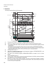
Chapter 49 Real-Time Clock
7.Q&A
7.8 What are interrupt-related registers?
RTC interrupt vector and level settings.
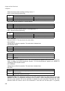
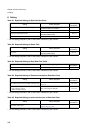
The following table shows the relationship between interrupt levels and vectors.
For details on interrupt levels and vectors, refer to “Chapter 24 Interrupt Control (Page No.311)”.
The interrupt request flags (INT0,INT1,INT2,INT3 and INT4) are not automatically cleared, so the software
must clear them by writing “0” to these flags before control is returned from interrupt processing.
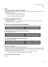
7.9 What interrupts are available and how are they selected?
There are four interrupt causes:
An interrupt request is made by ORing these four interrupt causes. Each cause can be selected with the
corresponding interrupt request enable bit.
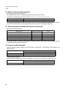
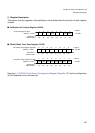
7.10 How do I enable interrupts?
Use the interrupt request enable bits (WTCR.INTE0, WTCR.INTE1, WTCR.INTE2, WTCR.INTE3 and
WTCER.INTE4).
To clear interrupt requests,
Use the interrupt request bits (WTCR.INT0, WTCR.INT1, WTCR.INT2, WTCR.INT3 and WTCER.INT4).
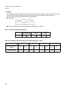
Interrupt vectors (Default) Interrupt level set bit (ICR[4.0])
#132 (0FFDECh) Interrupt level register ICR58 (047Ah)
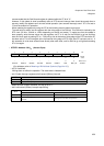
Interrupt cause Interrupt request bit
Interrupt request enable
bits
On counting seconds INT0 INTE0
On counting minutes INT1 INTE1
On counting hours INT2 INTE2
On counting days INT3 INTE3
On counting half-seconds INT4 INTE4
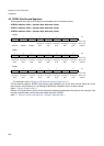
Setting Procedure
Interrupt request enable bits (INTE0, INTE1, INTE2, INTE3 and INTE4)
To disable interrupts Set the bit to “0”.
To enable interrupts Set the bit to “1”.
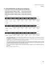
Setting Procedure
Interrupt request bits (INT0, INT1, INT2, INT3 and INT4)
To clear interrupt requests Write “0”.