809
Chapter 39 Programmable Pulse Generator
5.Operation
• Equation
Period = {Period value (PCSR) + 1} x Count clock
Duty = {Duty value (PDUT) + 1} x Count clock
Width up to pulse output = {Period value (PCSR) – Duty value (PDUT)} x Count clock
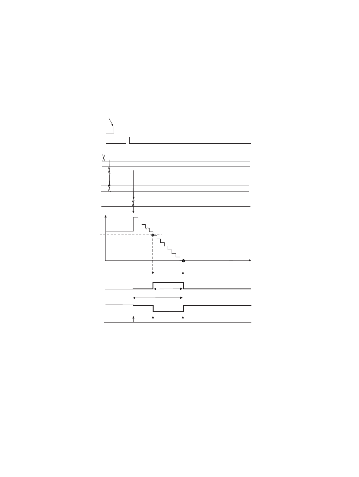
5.2 One-Shot Operation
In one-shot operation, one-shot pulses are generated from the PPG pin.
(1) Write a cycle value.
(2) Write a duty value and transfer the cycle value to buffers.
(3) Enable PPG operation.
(4) Generate an activation trigger.
(5) Load the cycle and duty values.
(6) Counter down count
(7) Down counter value and duty value
(8) Inverse the PPG pin output level.
(9) Counter down count
(10) Counter borrow
(11) Clear the PPG pin output level (return to normal).
(12) The operating sequence is now completed.
(See “8. Caution (Page No.821)”.)
PPG pin output
Interrupt
cause
Effective edge
Duty match
Counter borrow
Activation trigger
CNTE
Load
Enable count
Down count
value
(PTMR)
8000
Match
Borrow
0007
Buffer
(Duty value)
0007
PCSR
PDUT
Load
0007
Invert
Clear
(1)
(3)
(7)
Cycle
Duty
(6)
Down count
(8)
Down count
(9)
(10)
(11)
Normal
polarity
Inverted
polarity
8000
Buffer
(Cycle value)
(2)
(4)
(5)
(5)


