


7
Chapter 1 Introduction
4.How to Use This Document
4. How to Use This Document
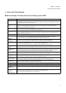
■ Main terminology: This table shows main terminology used for FR60.
Term Meaning
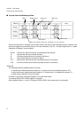
I-bus
32-bit-wide bus for internal instruction.
Since FR60 series employ internal Harvard architecture, instruction and data are independent bus. For I-bus,
Harverd/Prinston-bus-converter is connected.
D-bus
Internal 32-bit-wide data bus.
For D-bus, bit search module, Harverd/Prinston-bus-converter, R-bus interface (32-bit⇔16-bit Bus-
converter), and CAN modules are connected.
F-bus
Internal 32-bit-wide bus.
F-bus is connected to embedded Flash/ROM and embedded RAM.
R-bus
Internal 16-bit-wide data bus.
R-bus is connected to D-bus via R-bus-converter. For R-bus, peripheral function, I/O, clock generator and
interrupt controller are connected.
X-bus 32-bit-wide address and data bus. Via bus-converter for external bus, it accesses to external bus.
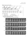
Main clock
(F
CL-MAIN
)
This a clock which acts as a benchmark for LSI operation triggered by high-speed-side oscillation.
This is connected to main clock oscillation stabilization timer and clock generator.
Subclock
(F
CL-SUB
)
This a clock which acts as a benchmark for LSI operation triggered by low-speed-side oscillation.
This is connected to sub oscillation stabilisation timer, real-time clock and clock generator.
Base clock
(Φ)
At the maximum speed, base clock has the same cycle as source oscillation. In PLL of the clock generator,
base clock has clock multiplied by 1, 2, 3, 4, 5, 6, 7 and 8 or clock divided by 2.
Base clock is basis clock which generates CLKB, CLKP and CKLT in the clock generator.
CPU clock
(CLKB)
CPU clock is the clock which is referred by CPU, embedded ROM, embedded RAM, bit search module and
internal bus (I-bus, D-bus, F-bus and X-bus) operations. Generated from the base clock in the clock generator.
Peripheral clock
(CLKP)
Peripheral clock is the clock which is referred by each peripheral function (peripheral functions other than bit
search module and CAN) connected to R-bus and R-bus, clock control, interrupt controller, I/O port and
external interrupt input d operations. Generated from the base clock in the clock generator.
External bus clock
(CLKT)
External bus clock is the clock which is referred by external expansion bus interface connected to X-BUS and
external clock output operations. Generated from the base clock in the clock generator.
CAN clock
(CLKCAN)
CAN clock is the clock which is referred by the CAN modules. Generated from the non modulated PLL
output clock to ensure operation within CAN network oscillation tolerances.
Main clock mode
Mode which runs based on main clock. This main clock mode has status such as main RUN, main sleep, main
stop, oscillation stabilization wait RUN, oscillation stabilization wait reset and program reset.
Subclock mode
Mode which runs based on subclock. This subclock mode has status such as sub RUN, sub sleep, sub stop,
subclock oscillation stabilization wait RUN and program reset.
Main RUN Main RUN is the status which is in main clock mode and also all circuits are operable.
Sub RUN Sub RUN is the status which is in subclock mode and also all circuits are operable.
Oscillation
stabilization time
Upon the reset (INITX, RST), return from stop, return from PLL abnormal operation, generation of watchdog
and during main clock stop, it takes oscillation stabilization time for main clock. Time base timer counts the
time.
Main clock
oscillation
stabilization wait
Wait time until main clock oscillates after main clock stops in subclock mode.
Main clock oscillation stabilization timer counts the time.