


309
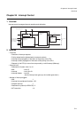
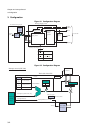
Chapter 23 Sub Oscillation Stabilisation Timer
8.Caution
8. Caution
• If the setting request (WIF=“1”) of the timer interrupt request flag and the writing timing where “0” is written to
the flag by the software occur simultaneously, the flag is set to “1”.
• If the interrupt request is enabled (WIE=“1”) after defeating a reset, and if the interval time is changed, be
sure to simultaneously set “0” to the interrupt request enable flag (WIF) and the clear bit (WCL).
• Read-modify-write
The interrupt request flag (WIF) is always read as “1” with the Read-modify-write.
• The setting initialization reset (INIT terminal input, watchdog reset) initializes the values of the timer interrupt
request bit (WIF), timer interrupt request enable bit (WIE), timer enable bit (WEN) and timer clear bit (WCL)
to “0”, but cannot initialize the interval period selection bit (WS[1:0]). Be sure to set it by the software.
• Setting the initial value of the sub oscillation stabilisation timer control register is possible using the
initialization reset (INIT terminal input, watchdog reset), but the operation initialization reset (Software reset)
holds the current value instead of initializing the value of the sub oscillation stabilisation timer control
register.
• The value for the oscillation stability wait time is an estimated value because the oscillation period of the
main clock oscillation is unstable for the beginning immediately after the oscillation has started.
• An unstable clock may be supplied to the entire device, and normal operation is not guaranteed if the
subclock is made to oscillate starting from subclock stopped state, and if the MCU operation mode is
switched from the main RUN to the sub-RUN mode without waiting until the subclock oscillation becomes
stable. Be sure to acquire the subclock oscillation stability wait time using the sub oscillation stabilisation
timer, etc. (If the main clock is selected as the clock source, the oscillation stability wait time for the subclock
may not be acquired.)
• The value for the oscillation stability wait time is an estimated value because the oscillation period of the
subclock is unstable for the beginning immediately after it has started.
• As the sub oscillation stabilisation timer stops while the subclock stops oscillating, a clock interrupt (interval
interrupt) is not generated either. If processing using the clock interrupt (interval interrupt) is performed,
enable the subclock oscillation. (Do not stop the subclock oscillation).
• The sub oscillation stabilisation timer counts up with the subclock. As a result, the timer stops counting
because the subclock stops oscillating under the following conditions.
• If the subclock is set that it stops in the stop mode (Subclock oscillation enable bit* =“1”), and then the
mode is switched to the stop mode, the sub oscillation stabilisation timer stops counting while in the stop
mode.
• If you want the sub oscillation stabilisation timer to continue counting while in stop mode, set the subclock
oscillation enable bit to “0” before switching the mode to the stop mode.
• If the subclock stop bit =“1” while in the subclock, and if the subclock is specified so that it stops
oscillating while the subclock is in operation, the sub oscillation stabilisation timer stops, too, while the
subclock is in operation.