


260
Chapter 18 Timebase Counter
7.Q&A
7. Q&A
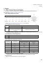
7.1 How do I setup the oscillation stabilization wait time that is generated automatically?
Use the oscillation stabilization wait time selection bits (STCR.OS[1:0]). (The following lists likely scenarios
and the required settings.)
• F2: Main clock divided by 2, or subclock
• In the case of an INIT pin input, operation defaults to “00” (F2 x 2
1
=main clock divided by 4).
• For other resets and when recovering from stop mode, the operation is in accordance with the specified
clock (main or sub) and oscillation stabilization wait time (OS[1:0]) setting.
• The count is performed by the timebase counter.
• Once the time is selected, it is not initialized except by a settings initialization triggered by the external
INIT pin.
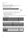
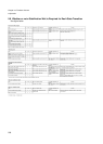
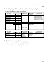
Scenario
Oscillation
stabilization wait
time selection bits
(OS[1:0])
Example oscillation stabilization wait time
after a reset (INIT) or on
recovering from stop mode
Oscillation
stabiliza-
tion
wait time
4.0MHz
Main clock
running
32.768kHz
Subclock
running
To not halt the main PLL or oscillator during stop mode
(No oscillation stabilization wait time required)
Set “00”.
Φ2 × 2
1
1.00µs61µs
To not stop the oscillator during external clock input or
stop mode
(Main PLL lock wait time)
Set “01”.
Φ2 × 2
11
1.0ms 62.5ms
When using an oscillator with a fast stabilization time
such as a ceramic resonator
(Oscillation stabilization wait time (medium))
Set to “10”.
Φ2 × 2
16
32ms 2.0s
When using a standard quartz oscillator
(Oscillation stabilization wait time (long))
Set to “11”.
Φ2 × 2
22
2s 128s