


1010
Chapter 55 Flash Security
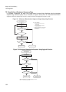
3.Flash Security Vectors
3. Flash Security Vectors
3.1 Vector addresses
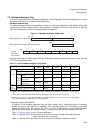
Two Flash Security Vectors (FSV1, FSV2) are located parallel to the Boot Security Vectors (BSV1, BSV2)
controlling the protection functions of the flash security module:
FSV1: 0x14:8000 BSV1: 0x14:8004
FSV2: 0x14:8008 BSV2: 0x14:800C
Remark: The addresses of both boot security vectors and flash security vectors depend on the size and the
data width configuration of the embedded flash memory. Therefore always check the appropriate datasheet if
the addresses shown here are valid for the product you are using.
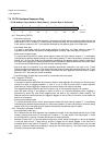
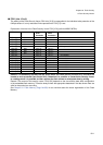
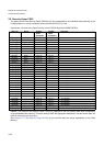
3.2 Security Vector FSV1
The setting of the Flash Security Vector FSV1 is responsible for the read and write protection modes and the
individual write protection of the 8 kByte sectors.
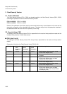
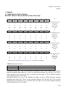
■ FSV1 (bits 31 to 16)
The setting of the Flash Security Vector FSV1 bits [31:16] is responsible for the read and write protection
modes.
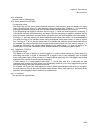
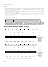
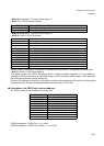
Explanation of the bits in the Flash Security Vector FSV1[31:16]:
FSV1[31:19] FSV1[18]
Write
Protection
Level
FSV1[17]
Write
Protection
FSV1[16]
Read
Protection
Flash Security Mode
set all to ‘0’ set to ‘0’ set to ‘0’ set to ‘1’ Read Protection (all device modes, except
INTVEC mode MD[2:0]=”000”)
set all to ‘0’ set to ‘0’ set to ‘1’ set to ‘0’ Write Protection (all device modes, without
exception)
set all to ‘0’ set to ‘0’ set to ‘1’ set to ‘1’ Read Protection (all device modes, except
INTVEC mode MD[2:0]=”000”) and Write
Protection (all device modes)
set all to ‘0’ set to ‘1’ set to ‘0’ set to ‘1’ Read Protection (all device modes, except
INTVEC mode MD[2:0]=”000”)
set all to ‘0’ set to ‘1’ set to ‘1’ set to ‘0’ Write Protection (all device modes, except
INTVEC mode MD[2:0]=”000”)
set all to ‘0’ set to ‘1’ set to ‘1’ set to ‘1’ Read Protection (all device modes, except
INTVEC mode MD[2:0]=”000”) and Write
Protection (all device modes except INTVEC
mode MD[2:0]=”000”)