


857
Chapter 41 Up/Down Counter
7.Q&A
7. Q&A
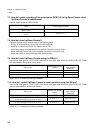
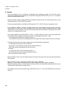
7.1 How do I select a bit length (8 or 16) of Up/Down Counter?
Use the 16 bit mode enable bit (UDCC.M16E).
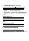
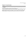
7.2 What types of count modes are available and how are they set?
There are four types of count modes:
Timer, Up/down count, Phase difference count (Multiply by 2 or 4)
Use the count mode selection bits (UDCC.CMS[1:0]) to set a count mode.
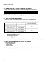
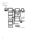
7.3 How do I select a count source for Up/Down Counter running in the timer mode?
Use the internal prescaler select bit (UDCC.CLKS).
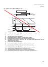
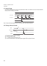
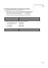
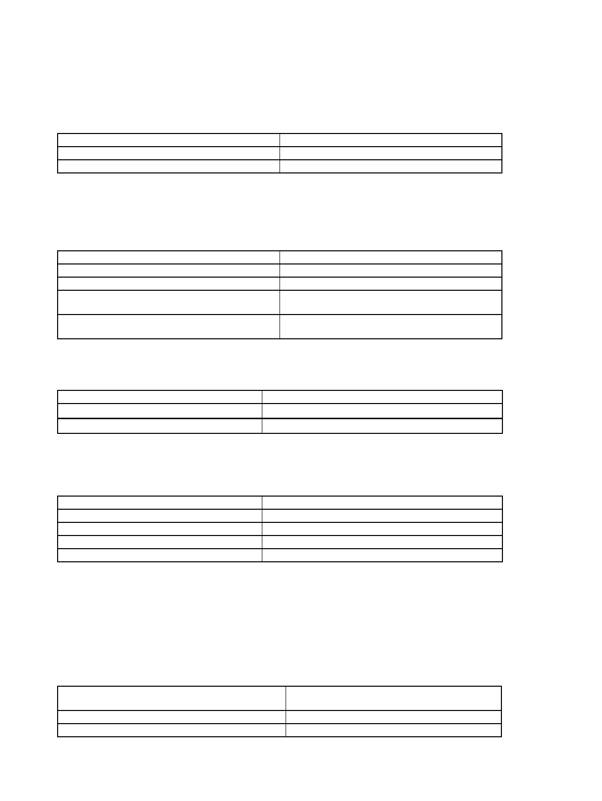
7.4 How do I select the edge with which Up/Down Counter running in the Up/down count
mode detects an input signal (AIN or BIN)?
Use count clock edge select bits (UDCC.CES[1:0]).
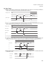
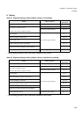
7.5 How do I set a value to Up/Down Counter?
A value can be set to Up/Down Counter by writing the value to the reload/compare register (RCR) and then
writing “1” to the counter write bit (UDCC.CTUT).
7.6 When the Up/Down Counter's count-up value agrees with the compare value
(RCR[0:1]), how do I enable clearing of Up/Down Counter the next time when the
counter counts up?
Use the up/down counter clear enable bit (UDCC.UCRE).
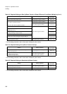
Up/Down Counter's bit length 16 bit mode enable bit (M16E)
To set the bit length to 8 Set the bit to “0”.
To set the bit length to 16 bit Set the bit to “1”.
Count mode Count mode selection bit (CMS[1:0])
To set the count mode to timer Set the bit to “00”.
To set the count mode to up/down count Set the bit to “01”.
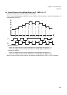
To set the count mode to phase difference count
(Multiply by 2)
Set the bit to “10”.
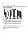
To set the count mode to phase difference count mode
(Multiply by 4)
Set the bit to “11”.
Count source for timer mode Internal prescaler select bit (CLKS)
To obtain the F
CLKP
divided by 2
Set the bit to “0”.
To obtain the F
CLKP
divided by 8
Set the bit to “1”.
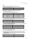
Edge to be detected by counter Count clock edge select bit (CES[1:0])
To disable detection Set the bit to “00”.
To enable detection of a falling edge Set the bit to “01”.
To enable detection of a rising edge Set the bit to “10”.
To enable detection of both edges Set the bit to “11”.
When the count-up value agrees with the compare
value and then Up/Down Counter counts up:
Up/down counter clear enable bit (UCRE)
To disable clearing of Up/Down Counter Set the bit to “0”.
To enable clearing of Up/Down Counter Set the bit to “1”.