


629
Chapter 32 USART (LIN / FIFO)
4.USART Registers
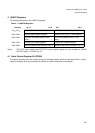
enabled, a transmission interrupt is generated. Write the next part of transmission data when a transmission
interrupt is generated or the TDRE bit is 1.
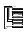
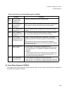
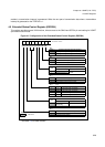
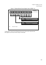
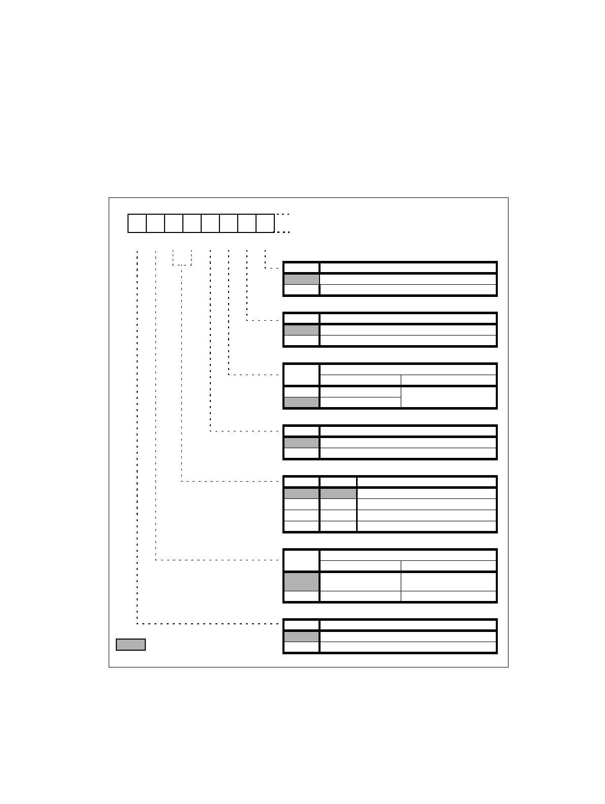
4.5 Extended Status/Control Register (ESCR04)
This register provides several LIN functions, direct access to the SIN04 and SOT04 pin and setting for USART
synchronous clock mode.
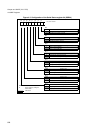
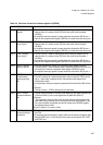
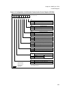
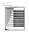
Figure 4-5 Configuration of the Extended Status/Control Register (ESCR04)
* see table 4-6 for RMW access!
15 14 13 12 11 10 9 8
Initial value
0 0 0 0 0 1 0 0
B
R/W R/W R/W R/W R/WR/W R/W
R/W
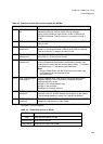
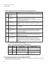
bit8
SCES Sampling Clock Edge Selection (Mode 2)
0 Sampling on rising clock edge (normal)
1 Sampling on falling clock edge (inverted clock)
bit9
CCO Continuous Clock Output (Mode 2)
0 Continuous Clock Output disabled
1 Continuous Clock Output enabled
bit10
SIOP
Serial Input / Output Pin Access
write (if SOPE = “1”) read
0 SOT04 is forced to “0” reading theactual valueof
SIN04
1 SOT04 is forced to “1”
bit11
SOPE Enable Serial Output pin direct Access
0 Serial Output pin direct access disable
1 Serial Output pin direct access enable
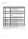
bit12 bit 13
LBL0 LBL1 LIN break length
0 0 LIN break length 13 bit times
1 0 LIN break length 14 bit times
0 1 LIN break length 15 bit times
1 1 LIN break length 16 bit times
bit14
LBD
LIN break detected
write read *
0 Clear LIN break
detected flag
No LIN break detected
1 ignored LIN break detected
bit15
LBIE LIN break detection Interrupt enable
0 LIN break interrupt disable
1 LIN break interrupt enable
R/W : Readable and writable
: Initial value