


265
Chapter 19 Timebase Timer
4.Register
4. Register
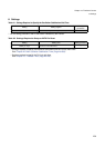
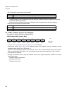
4.1 TBCR: Timebase Timer Control Register
This register is used to set timebase timer interrupt control, reset/ standby operation option etc.
Note: Refer also to “Chapter 10 Standby (Page No.155)”.
• TBCR: Address 0482h (Access: Byte)
(Refer to “Meaning of Bit Attribute Symbols (Page No.10)” for the attributes.)
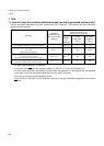
• Bit7: Timebase timer interrupt request flag
• An interrupt request is generated if the timebase timer interrupt request enable bit is “1”, and if the
timebase timer interrupt request flag is “1”.
• Bit6: Timebase timer interrupt request enable
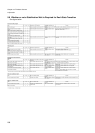
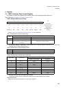
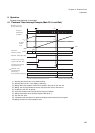
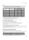
• Bit5-3: Selecting the timebase timer interval time
• Be sure to set the interval time before an interrupt.
(Oscillation stability wait time used when returning to the stop caused by an interrupt)
• Bit2: Reserved bit
Writing does not affect the operation. The read value is indefinite.
7 6 5 4 3 2 1 0 bit
TBIF TBIE TBC2 TBC1 TBC0 --- SYNCR SYNCS
00XXXX00
Initial value
(INIT terminal input,
watchdog reset)
00XXXXXX
Initial value
(the software reset)
R(RM1),W R/W R/W R/W R/W RX/WX RX/WX R/W Attribute
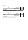
TBIF
Operation
Read Write
0 With no interrupt request Flag is cleared
1
With interrupt request
(The interval time set by the timebase timer
has elapsed)
Writing does not affect operation
TBIE Operation
0 Disabling the timebase timer interrupt request
1 Enabling the timebase timer interrupt request
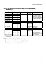
TBC2-TBC0 Interval time
Example
While the main clock operates
(4.0MHz, PLL8 multiply)
While the subclock operates
(32.768kHz)
000
Φ × 2
11
64.0µs
62.5ms
001
Φ × 2
12
128µs
125ms
010
Φ × 2
13
256µs
250ms
011
Φ × 2
22
131ms 128s
100
Φ × 2
23
262ms 256s
101
Φ × 2
24
524ms 512s
110
Φ × 2
25
1048ms 1024s
111
Φ × 2
26
2097ms 2048s