


1004
Chapter 54 Flash Memory
7.Auto Algorithms
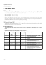
7.4 FLCR: Hardware Sequence Flag
• FLCR: Address. Any address in Flash memory. (Access: Byte or half-word)
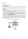
• bit 7: Data polling (DPOLL)
• Auto write under way
If data is read while the auto write algorithm is executing, the Flash memory outputs the data with the last
value written to bit 7 inverted. If a read access is performed after the auto-write algorithm finishes, the
Flash memory outputs the bit 7 of the address indicated by the address signal for the read data.
• Auto erase under way
If a read is performed while the auto-erase algorithm is executing, the Flash memory outputs “0”,
regardless of the address indicated by the address signal. Similarly, upon termination it outputs “1”.
• Sector erase suspend mode
If a read is performed while in sector erase suspend mode, the Flash memory outputs “1” if the address
indicated by the address signal belongs to a sector being erased. If it does not belong to the sector being
erased, bit 7 of the value read from the address indicated by the address signal is output. Referring to
this value while toggling bit 6 (described below) makes it possible to determine whether the current sector
is in sector erase-suspend state, and which sectors are being erased.
• Note that when the operation of an Auto Algorithm approaches termination, the value of bit 7 (data
polling) changes asynchronously. This means that Flash memory sends the operating status to bit 7, then
sends this data next. When the Flash memory terminates the Auto Algorithm, and also when it outputs
data set in bit 7, the other bits are still undefined.
• The defined data for other bits can be read by successfully executing reads.
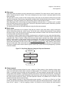
• bit 6: Toggle bit (TOGGLE)
• Auto write/erase under way
If successive reads are performed while the auto-write or erase algorithm is executing, the Flash memory
outputs the result of toggling between “1” and “0” to bit 6. After the auto write or erase algorithm
terminates, bit 6 stops toggling in response to successive reads, and outputs valid data.
The toggle bit becomes effective after the final write cycle of the command sequence in question.
Note that when writing, if an attempt is made to write to an overwrite-protected sector, toggling is
performed for about 2us, after which toggling ends; the data is not overwritten. When erasing, if all
selected sectors are write-protected, the toggle bit toggles for about 100us, the returns to read mode; the
data is not overwritten.
• Sector erase suspend mode
If a read is performed while in sector erase suspend mode, the Flash memory outputs “1” if the address
indicated by the address signal belongs to a sector being erased. If it does not belong to the sector being
erased, bit 6 of the value read from the address indicated by the address signal is output.
• bit 5: Timing limit exceeded (TLOVER)
• Auto write/erase under way
Bit 5 indicates that the Auto Algorithm has exceeded the length of time stipulated internally by the Flash
memory (internal pulse count). In this state, bit 5 outputs “1”. In other words, if this flag outputs “1” while
an Auto Algorithm is running, it means that the write or erase has failed.
Attempts to write to bit 5, or an unerased non-flag area, will fail. When this happens, it will not be possible
to read set data from bit 7 (data polling), and bit 6 (toggle bit) will remain toggled. If the time limit is
exceeded while in this state, bit 5 outputs “1”. Note that this means that the Flash memory was not used
properly; it does not mean that something is wrong with the Flash memory. If the Flash memory reaches
this state, execute the reset command.
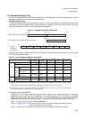
7 6 5 4 3 2 1 0 bit
DPOLL TOGGLE TLOVER - SETIMR TOGGL2 - -
- - - - - - - - Initial value
R R R RX R R RX RX Attribute