


380
Chapter 26 DMA Controller
6.DMA External Interface
■ Timing of Demand Transfer
For demand transfer, set the DMA start source to level detection. Although there is no rule for starting,
synchronize with RD/WRn of the DMA transfer when stopping a transfer. The sense timing is the rise of MCLK in
the final external access.
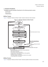
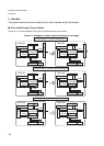
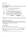
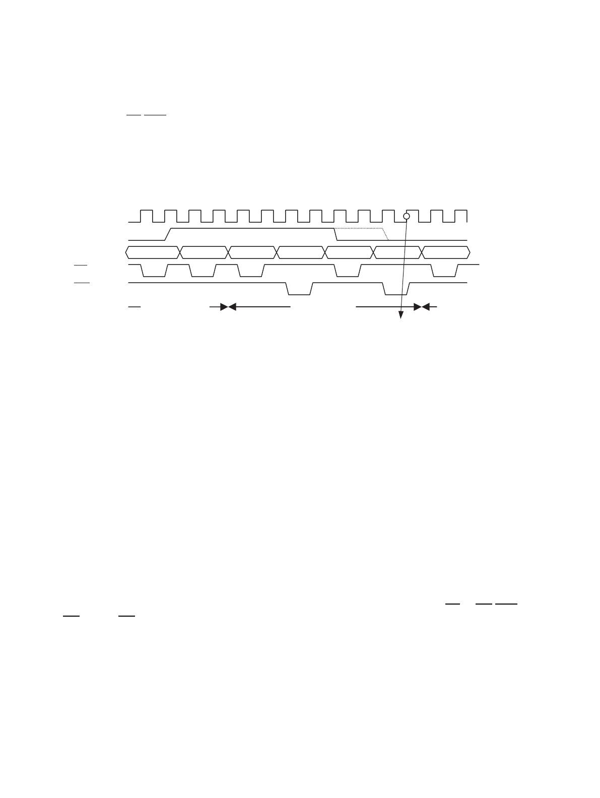
Figure 6-2"Timing Chart for Demand Transfer" shows the timing chart for demand transfer.
Figure 6-2 Timing Chart for Demand Transfer
Note:
In this case, because 2-cycle transfer is used and the transfer source and transfer destination are an external
area, negate from the fall of #RD2 to before the final MCLK rise of #WR2 to stop the two DMA transfer
operations.
6.2 FR30 Compatible Mode of DACK
FR30 compatible mode of DACK makes the DACK timing identical to the timing of DMA used in
FR30 series devices. This section provides the timing charts for the DACK pin in FR30 compat-
ible mode for the following examples of transfer mode setting:
• 2-cycle transfer mode
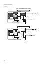
• Fly-by transfer mode
■ Transfer Mode Settings
Set the transfer mode using the PFR register corresponding to the DACK pin.
When setting PFR, match the transfer mode (2-cycle transfer/fly-by transfer) of the corresponding DMA channel.
Note:
If 2-cycle transfer is set in FR30 compatible mode, the transfer is synchronized with RD or WR/WRn. To use
WR, enable WR by setting 0x1x
B
for TYPE3-0 of the external interface ACR register.
● 2-cycle transfer mode
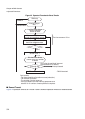
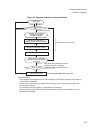
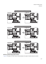
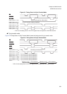
Figure 6-3"Timing Chart in 2-Cycle Transfer Mode" shows the timing chart in 2-cycle transfer mode.
When a DREQx level is requested (for 2-cycle transfer)
MCLK
DREQ
A24 to 0 #RD1 #WR1 #RD2 #WR2
RD
WR
CPU operation DMA transfer
Sense point of the 3rd transfer request
CPU