


814
Chapter 39 Programmable Pulse Generator
7.Q & A
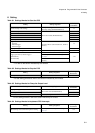
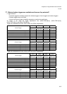
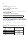
7.5 What count clocks are available and how are they selected?
Count clock selection
The count clock is selectable out of the four choices listed below.
Use the count clock selection bit (PCN.CKS[1:0]).
(See “8. Caution (Page No.821)”.)
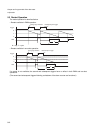
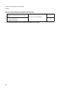
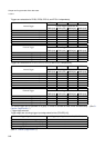
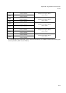
7.6 How do I clamp the PPG pin output level?
PPG output mask selection
The level of PPG pin output can be clamped.
Use the PPG Output Mask Selection bit (PCN.PGMS) and the duty value (PDUT) to set.
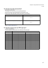
PPG pin output can be set to all “L”. (when OSEL=“0”)
PPG pin output can be set to all “H”. (when OSEL=“0”)
PPG output will also equal all “H” if “0” is set in both the PPG Period Setting Register (PCSR) and PPG Duty
Setting Register (PDUT). (when OSEL=“0”)
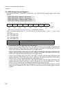
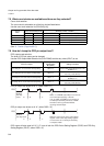
Count
Clock
Count Clock Selection Bit (Example) CLKP = 32 MHz
CKS1 CKS0 Count Clock Period (1 - FFFFh)
CLKP 0 0 32MHz 62.5ns - 2.048µs
CLKP/4 0 1 8MHz 250ns - 8.192µs
CLKP/16 1 0 2MHz 1µs - 32.76ms
CLKP/64 1 1 500kHz 4µs - 131.0ms
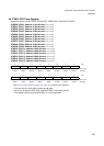
PPG Pin Output
PPG Output Polarity
Specification
Bit (OSEL)
Setting Procedure
To clamp the “L” level under normal polarity When “0”
Set the PPG Output Mask Selection bit
(PGMS) to “1”.
To clamp the “H” level under normal polarity When “0”
Period value (PCSR) =
Set a duty value (PDUT).
To clamp the “H” level under inverted polarity When “1”
Set the PPG Output Mask Selection bit
(PGMS) to “1”.
To clamp the “L” level under inverted polarity When “1”
Period value (PCSR) =
Set a duty value (PDUT).
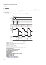
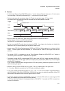
PPG
Reduce
the duty
value
Write "1" to PGMS (mask bit) on occurrence
of an interrupt caused by a borrow.
If "0" is written to PGMS on occurrence of
an interrupt caused by a borrow, a PWM
waveform can be generated without
incurring hazard output.
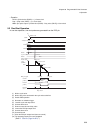
PPG
Reduce
the duty value
Write the same value as the cycle setting
register value to the duty setting register
on occurrence of an interrupt caused by
a compare match.