


902
Chapter 44 A/D Converter
6.Q & A
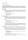
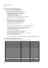
6.3 How do I set a conversion time?
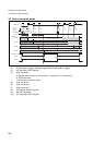
Use Conversion Time Setting registers ADCT to set.
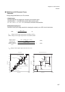
[bit 15 to 10] CT5-0 (A/D conversion time set)
These bits specify clock division of conversion time.
Setting "000001" means one division (=CLKP).
Do not set these bits "000000".
Initialized these bits to "000100" by reset.
Conversion time = CT value * CLKP cycle * 10 + (4 * CLKP)
Remarks : Do not set conversion time over 500 us.
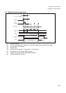
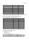
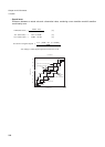
[bit 9 to 0] ST9-0 (Analog input sampling time set)
These bits specify sampling time of analog input.
Initialized these bits to "0000101100" by reset.
Sampling time = ST value * CLKP cycle
Remarks : Do not set sampling time below 1.2 us when AVCC is below 4.5 V.
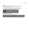
Necessary sampling time and ST value are calculated by following.
Necessary sampling time (Tsamp) = (Rext + Rin) * Cin * 7
ST9 to ST0 = Tsamp / CLKP cycle
ST has to be set that sampling time is over Tsamp.
ex. CLKP = 32MHz, AVCC >= 4.5V, Rext = 200K
Tsamp = ( 200 * 103 + 2.52 * 103 ) * 10.7 * 10-12 * 7 = 15.17 [us]
ST = 15.17-6 / 31.25-9 = 485.44
ST has to be set over 486
D
(111100110
B
).
Tsamp is decided by Rext. Thus conversion time should be considered together with Rext.
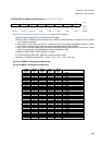
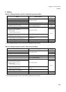
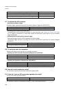
6.4 How do I enable analog pin input?
Use Port Function register PFR and Extra Port Function register EPFR.
Operation PFR setting EPFR setting
To program the AN0 pin as an input PFR29.0 = ‘1’ EPFR29.0 = ‘0’
To program the AN1 pin as an input PFR29.1 = ‘1’ EPFR29.1 = ‘0’
To program the AN2 pin as an input PFR29.2 = ‘1’ EPFR29.2 = ‘0’
To program the AN3 pin as an input PFR29.3 = ‘1’ EPFR29.3 = ‘0’
To program the AN4 pin as an input PFR29.4 = ‘1’ EPFR29.4 = ‘0’
To program the AN5 pin as an input PFR29.5 = ‘1’ EPFR29.5 = ‘0’
To program the AN6 pin as an input PFR29.6 = ‘1’ EPFR29.6 = ‘0’
To program the AN7 pin as an input PFR29.7 = ‘1’ EPFR29.7 = ‘0’
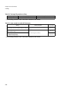
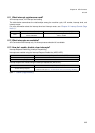
To program the AN8 pin as an input PFR28.0 = ‘1’ EPFR28.0 = ‘0’
To program the AN9 pin as an input PFR28.1 = ‘1’ EPFR28.1 = ‘0’
To program the AN10 pin as an input PFR28.2 = ‘1’ EPFR28.2 = ‘0’
To program the AN11 pin as an input PFR28.3 = ‘1’ EPFR28.3 = ‘0’
To program the AN12 pin as an input PFR28.4 = ‘1’ EPFR28.4 = ‘0’
To program the AN13 pin as an input PFR28.5 = ‘1’ EPFR28.5 = ‘0’
To program the AN14 pin as an input (*) PFR28.6 = ‘1’ EPFR28.6 = ‘0’
To program the AN15 pin as an input (*) PFR28.7 = ‘1’ EPFR28.7 = ‘0’
To program the AN16 pin as an input PFR27.0 = ‘1’ EPFR27.0 = ‘1’
To program the AN17 pin as an input PFR27.1 = ‘1’ EPFR27.1 = ‘1’