139
Chapter 9 Reset
1.Overview
Chapter 9 Reset
1. Overview
When a reset is triggered, the device halts the program and all hardware operation, and then initializes all
states. This state is called a reset.
When the reset trigger condition is removed, the device changes from this initialized state to restart the
program and hardware operation. The series of steps from removal of the reset condition until operation starts
is called the reset cancellation sequence.
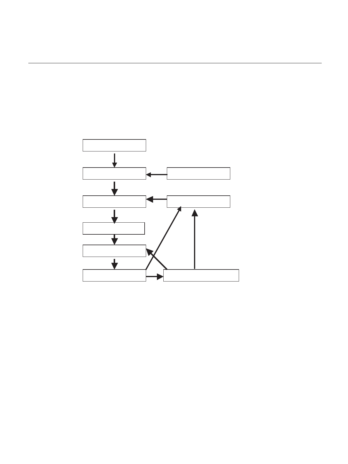
Figure 1-1 Flow of Reset Operation
2. Features
• Types of reset
• INIT pin input: Settings initialization reset (INIT)
• RST pin input: Operation initialization reset (RST)
• HSTX pin input: Settings initialization reset (INIT)
• Watchdog reset: Settings initialization reset (INIT)*
• Software reset: Operation initialization reset (RST)
• Low Voltage reset: Setting initialization reset (INIT)
*: Although a watchdog reset triggers the same settings initialization reset (INIT) as the INITX pin input, it does
not initialize the oscillation stabilization time selection bits (OS[1:0]) and reset cause flags (INIT, HSTB, WDOG,
ERST, SRST and LINIT).
• Cause of reset can be determined
• The cause of the previous reset is stored in a series of flags (INIT, HSTB, WDOG, ERST, SRST and
LINIT) in the RSRR register.
• Operation after reset condition is removed
• Operation mode: Determined by the mode pins and mode data.
RUN
Software reset instruction
Oscillation stabilization
wait reset
Operation initialization
reset
Settings initialization reset
Power ON
INIT pin input
Watchdog timeout
From any state


