


896
Chapter 44 A/D Converter
4.Operation of A/D Converter
4. Operation of A/D Converter
The A/D converter operates using the successive approximation method with 10-bit or 8-bit resolution. As only
one 16-bit register is provided to store conversion results, the conversion data register (ADCR0 and ADCR1) is
updated each time conversion completes. Therefore, as the A/D converter on its own is not suitable for
performing continuous conversion, it is recommended that you use the DMA service. The following describes the
operation modes.
■ Single Mode
In single conversion mode, the analog input signals selected by the ANS bits and ANE bits are converted
in order until the completion of conversion on the end channel determined by the ANE bits. A/D
conversion then ends. If the start channel and end channel are the same (ANS=ANE), only a signal
channel conversion is performed.
ex.
ANS=00000b, ANE=00011b
Start -> AN0 -> AN1 -> AN2 -> AN3 -> End
ANS=00010b, ANE=00010b
Start -> AN2 -> End
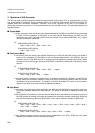
■ Continuous Mode
In continuous mode the analog input signals selected by the ANS bits and ANE bits are converted in
order until the completion of conversion on the end channel determined by the ANE bits, then the
converter returns to the ANS channel for analog input and repeats the process continuously. When
the start and end channels are the same (ANS=ANE), conversion is performed continuously for that
channel.
ex.
ANS=00000b, ANE=00011b
Start -> AN0 -> AN1 -> AN2 -> AN3 -> AN0 ... -> repeat
ANS=00010b, ANE=00010b
Start -> AN2 -> AN2 -> AN2 ... -> repeat
In continuous mode, conversion is repeated until '0' is written to the BUSY bit. (Writing '0' to the BUSY bit
forcibly stops the conversion operation.) Note that forcibly terminating operation halts the current
conversion during mid-conversion. (If operation is forcibly terminated, the value in the conversion
register is the result of the most recently completed conversion.)
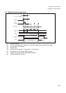
■ Stop Mode
In stop mode the analog input signal selected by the ANS bits and ANE bits are converted in order, but
conversion operation pauses for each channel. The pause is released by applying another start
signal.
At the completion of conversion on the end channel determined by the ANE bits, the converter returns to
the ANS channel for analog input signal and repeats the conversion process continuously. When the
start and end channel are the same (ANS=ANE), only a signal channel conversion is performed.
ex.
ANS=00000b, ANE=00011b
Start -> AN0 -> stop -> start -> AN1 -> stop -> start -> AN2 -> stop -> start -> AN3 -> stop ->
start -> AN0 ... -> repeat
ANS=00010b, ANE=00010b
Start -> AN2 -> stop -> start -> AN2 -> stop -> start -> AN2 ... -> repeat
In stop mode the startup source is only the source determined by the STS1, STS0 bits. This mode
enables synchronization of the conversion start signal.