


972
Chapter 50 Subclock Calibration Unit
5.Register Description
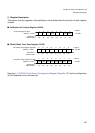
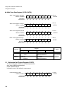
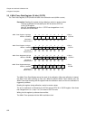
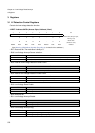
5.3 4 MHz Timer Data Register (24 bits) (CUTR)
The Timer Data Register (CUTR) holds the value of the calibration result (4MHz counter)
Precaution: Reading this register during calibration, results in random values.
The end of calibration is indicated by the INT-bit and the STRT-bit
in the CUCR-register.
After INT has changed from 0 to 1 / STRT has changed from 1 to 0,
the value of CUTR is valid.
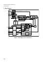
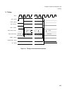
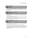
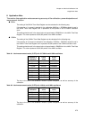
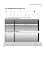
The 4MHz Timer Data Register stores the result of the calibration. When the calibration is started,
the 4MHz Timer starts counting up from zero. When the 32kHz/100kHz Timer reaches zero, the
4MHz Timer stops counting and the register holds the calibration result until the next calibration is
triggered by software.
Reading this register during calibration, results in random values.
The end of calibration is indicated by the INT-bit and the STRT-bit in CUCR-register. After these
bits changed from 0 to 1, resp. 1 to 0, the value of CUTR is valid.
Writing into this register by software has no effect.
The 4MHz Timer operates with the 4MHz oscillation clock.
TDR7 TDR6 TDR5 TDR4 TDR3 TDR2 TDR1 TDR0
⇐ Bit no.
Read/write ⇒
(R) (R) (R) (R) (R) (R) (R) (R)
Default value⇒
(0) (0) (0) (0) (0) (0) (0) (0)
Address : 0004B7
H
765432 10
CUTR2L
4MHz
Timer Register2 low byte
TDR15TDR14 TDR13TDR12 TDR11TDR10
TDR9 TDR8
⇐ Bit no.
Read/write ⇒
(R) (R) (R) (R) (R) (R) (R) (R)
Default value⇒
(0) (0) (0) (0) (0) (0) (0) (0)
4MHz Timer Register2 high byte
Address : 0004B6
H
15 14 13 12 11 10 9 8
CUTR2H
TDR23TDR22TDR21TDR20 TDR19TDR18 TDR17TDR16
⇐ Bit no.
Read/write ⇒
(R) (R) (R) (R) (R) (R) (R) (R)
Default value⇒
(0) (0) (0) (0) (0) (0) (0) (0)
Address : 0004B5
H
765432 10
CUTR1L
4MHz
Timer Register1 low byte
------
--
⇐ Bit no.
Read/write ⇒
(R) (R) (R) (R) (R) (R) (R) (R)
Default value⇒
(0) (0) (0) (0) (0) (0) (0) (0)
4MHz Timer Register1 high byte
Address :
0004B4H
15 14 13 12 11 10 9 8
CUTR1H