


1014
Chapter 55 Flash Security
4.Register
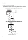
Remark: The Flash Security Vector Re-Fetch sequence is especially intented to be used after a chip erase
command to update the security status without the need of applying an external INITX reset or after changing
the status of the FSV1 security vector.
Remark: For both Security Vector Re-Fetch and CRC32 it is not recommended to start these sequences from
programs located in the Flash Memory itself.
Remark: Before starting the CRC32 checksum it is recommended to set the RC oscillation in the 2MHz
operation mode to avoid long runtimes. See the RCSEL bit in Chapter 4.1 Clock Monitor Configuration
Register (Page No.943).
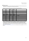
• Bit31-0: CRC32 checksum result
This register contains the CRC32 checksum result after completion of the CRC32 checksum sequence (the
sequence completion is indicated by FSCR1.RDY). The CRC checksum is calculated in a standard CRC32/
AAL5 algorithm with the polygon x^32+x^26+x^23+x^22+x^16+x^12+x^11+x^10+x^8+x^7+x^5+x^4+x^2+x+1.
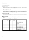
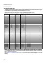
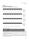
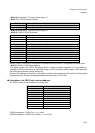
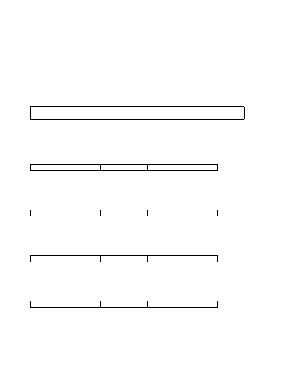
■ FSCR1: Address 7104h (Access: Byte (read), Word (write))
(See “Meaning of Bit Attribute Symbols (Page No.10)” for details of the attributes.)
CRC31-CRC0 Function
CRC32 Checksum (read only)
31 30 29 28 27 26 25 24 bit
-------RDY
00000000
Initial value (
INIT pininput,
watchdog reset)
XXXXXXXX
Initial value
(Software reset)
R0/WX R0/WX R0/WX R0/WX R0/WX R0/WX R0/WX R Attribute
23 22 21 20 19 18 17 16 bit
----CSZ3 CSZ2 CSZ1 CSZ0
00000000
Initial value (
INIT pininput,
watchdog reset)
XXXXXXXX
Initial value
(Software reset)
R0/WX R0/WX R0/WX R0/WX R/W R/W R/W R/W Attribute
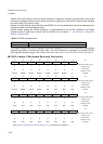
15 14 13 12 11 10 9 8 bit
CSA15 CSA14 CSA13 CSA12 CSA11 CSA10 CSA9 CSA8
00000000
Initial value (
INIT pininput,
watchdog reset)
XXXXXXXX
Initial value
(Software reset)
R/W R/W R/W R/W R/W R/W R/W R/W Attribute
76543210 bit
CSA7 CSA6 CSA5 CSA4 CSA3 CSA2 CSA1 CSA0
00000000
Initial value (
INIT pininput,
watchdog reset)
XXXXXXXX
Initial value
(Software reset)
R/W R/W R/W R/W R/W R/W R/W R/W Attribute