


3
Chapter 1 Introduction
2.Instruction for Users
2. Instruction for Users
■ Clock Controls
By inputting “L” to INIT, ensure clock oscillation stabilization time.
■ Switching of dual-purpose port
Use PFR (Port function register) to switch between PORT and dual-purpose port.
■ Low-power-consumption mode
• For standby mode, enable synchronous standby (TBCR.SYNCS=“1”) and then use the following sequences.
In addition, after returning from standby, set I flag, ILM and ICR in order to branch to interrupt handler which
triggered the return.
• If you use monitor debugger, you should avoid the following.
• Do not set breakpoints for command sequence above.
• Do not conduct stepwise execution for command sequence above.
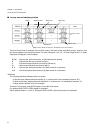
■ Power-on sequence
Power-on and power-off sequence valid for MB91V460 Rev.A. Please review the datasheets of the flash
devices for a valid power-on and power-off sequence on those devices.
Power-on sequence: (1) VDD5 , VDD35, HVDD5, VDD5R (2) AVCC, AVRH, V0-V3
Power-off sequence: (1) AVCC, AVRH, V0-V3 (2) VDD5 , VDD35, HVDD5, VDD5R
The power supply V3 for LCD must not exceed VDD5. The power-on of V3 should be carried out after power-
on of VDD5R and VDD5. To power on analogue power supply AVCC and analogue signal, power VDD5R and
VDD5 on before.
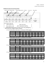
■ Power supply operating conditions
Power supply recommendation valid for MB91V460 Rev.A. Please review the datasheets of the flash devices
for a recommendation of the power supply conditions on those devices.
[VDD5 = HVDD5 = AVCC] >= VDD35. This is the recommended condition.
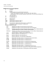
value_of_standby is a write data to STCR#value_of_standby, R0
#_STCR, R12
R0, @R12
@R12, R0
@R12, R0
_STCR is the STCR address. (481H)
Write to Standby Control Register (STCR).
STCR read for synchronous standby.
Dammy read STCR again.
NOP x 5 for timing adjustment.
(LDI
(LDI
STB
LDUB
LDUB
NOP
NOP
NOP
NOP
NOP