907
Chapter 44 A/D Converter
7.Caution
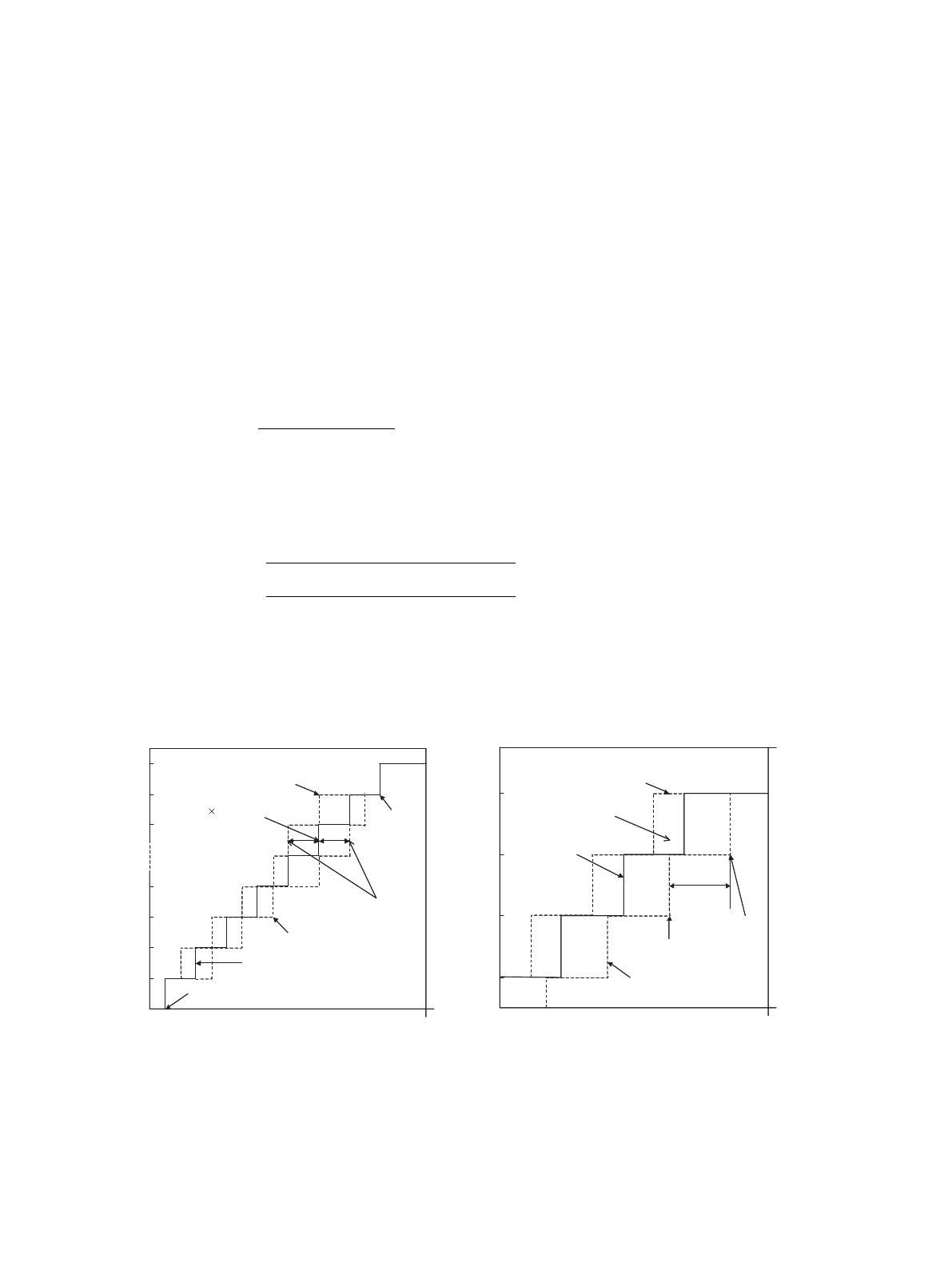
■ Definitions of A/D Converter Terms
• Resolution
Analog change identifiable to an A/D converter.
• Linearity error
Deviation between the straight line connecting zero transition point
(00 0000 0000 <- -> 00 0000 0001) and full-scale transition point
(11 1111 1110 <- -> 11 1111 1111) from actual conversion characteristics
• Differential linearity error
Deviation of the input voltage required for changing the output by one LSB, from its ideal value
1LSB
=
VFST - VOT
[V]
1022
V
OT
: Voltage at which digital output transit from (000)
H
to (001)
H
VV
FST
: Voltage at which digital output transit from (3FE)
H
to (3FF)
H
Digital output N
Linearity error
=
V
NT
- {1LSB × (N-1) + V
OT
}
[LSB]
1LSB
Digital output N
Differentiallinearity
error
=
V(N+1)T - VNT
-1 [LSB]
1LSB
V
NT
: Voltage at which digital output transit from (N+1) to N
3FF
3FE
3FD
004
003
002
001
V
OT (Measurement value)
Ideal characteristics
Actual conversion characteristics
VNT
(Measurement
value)
{1LSB (N-1)+V
OT}
AVss
AVRH
Digital output
Analog input
Linearity error
V
FST
(Measurement
value)
-
Actual conversion characteristics
N+1
N
N-1
N-2
Actual conversion characteristics
Actual conversion characteristics
VNT
AVss
V
FST
2
VNT
AVss
(Measurement
value)
AVRH
Digital output
Analog input
Differentional linearity error


